CONCURRENT & PARALLEL FORCES
CONCURRENT & PARALLEL FORCES
The purpose of this is to give quick reference to information or to use in an emergency (like if your text has accidentally been left under your desk at school).
This is NOT intended to replace reading the text with its excellent photographs, diagrams, charts, and tables.
COMPOSITION OF FORCES
4.1 Describing Forces In Chapter 3, we studied the relationship between forces and motion. Now we shall take a look at some other characteristics of forces, and see how these characteristics are used in solving force problems.
When you push a door shut with your hand, your hand exerts a force on the door. The door also exerts a force on your hand. When you sit in a chair, you push on the chair and the chair pushes on you. In both of these cases, there is physical contact between the objects that are exerting forces on each other.
Forces can also be exerted without such physical contact. While an object is falling toward the earth, the earth exerts a gravitational force on the object and the object exerts a gravitational force on the earth. Yet there is no physical contact between the earth and the falling object.
These examples illustrate several important characteristics of forces:
1 . A net force will change the state of motion of an object. The door moved because the force exerted by your hand was sufficient to overcome friction and other forces acting on the door. An object falls because a force is pulling it toward the earth. As we saw in Chapter 3, the application of a net force to an object always produces an acceleration.
2. Forces can be exerted through long distances. Gravitational and magnetic forces have this characteristic.
3. Forces always occur in pairs. When one object pushes or pulls on another object, there is a force on each of the two objects. In the given examples, the two objects were your hand and the door, you and the chair, and the falling object and the earth.
4. In each pair of forces, the two forces act in exactly opposite directions. You pushed on the door, and the door pushed back. You pushed down, and the chair pushed up. The earth pulled the falling object toward the earth's center, and the object pulled the earth toward the object's center.
Now let us see how the magnitudes of forces are measured. (You will remember from Chapter 3 that forces are vector quantities and have both magnitude and direction.)
When an object is suspended from a spring, it is pulled toward the earth by the force of gravitation. The spring stretches until the restoring force of the spring is equal to the force of gravitation on the object. Another object having the same weight stretches the spring by the same amount. Both objects together stretch the spring twice as far, and an object with three times the weight stretches it three times as far, etc.
This characteristic of coiled springs, that the amount of stretch is proportional to the force pulling on the spring, means that we may use the amount of stretch to measure the size of a force. A device that measures forces in this way is called a spring balance. Forces may also be measured with devices other than spring balances. The results of such measurements can always be expressed in terms of newtons.
4.2 Combining Force Vectors Since forces have both magnitude and direction, they are vector quantities. When a vector is used to represent a force, the magnitude of the force is represented by the length of the arrow. The direction of the force may be deduced from the physical situation. For example, suppose a barge is being towed through still water by a tugboat. The tugboat applies a force of 10,000 n to the barge through the towline. The length of the arrow representing the force is proportional to the magnitude of the force, 10,000 n.
The point of application of the force is the point at which the rope is attached to the barge. A long rope can transmit only a pull in a direction along its length. It cannot transmit a push or a sideways force. The rope is in the direction of the force. The arrow shows this direction.
Do NOT forget to put heads on your arrows !!!
Force vectors are treated like velocity vectors. For example, suppose two tugboats are attached to the same barge. Tugboat A is pulling with a force of 10,000 n and tugboat B is pulling with a force of 7,500 n in the same direction.
Figures 4-3 & 4 represents this situation with vectors.
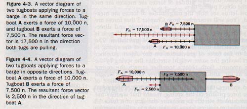
The resultant force vector is 17,500 n in the direction of the towline. Figure 4-4 shows a vector diagram representing two tugboats pulling in opposite directions on a barge. Even though the forces act on extended objects such as opposite ends of the barge, the vectors may be considered as acting at the same point. The resultant force vector is 2,500 n in the direction of tugboat A.
When two or more forces act on the same point at the same time they are called concurrent forces. A resultant force is a single force that has the same effect as two or move concurrent forces. When two forces act concurrently in the same or in opposite directions, the resultant has a magnitude equal to the algebraic sum of the forces and acts in the direction of the greater force.
When two forces act concurrently at an angle other than Oo or 180o, the resultant can be found by the parallelogram method, as in the velocity vector problems in Chapter 3.
Suppose one force of 10.0 n acts eastward upon an object. Another force of 15.0 n acts southward upon the same point. Since these forces act concurrently upon the same point, the vector diagram is constructed with the tails of both vectors at O, See Figure 4-5. FE tends to move the object eastward. FS tends to move the object southward.
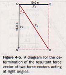
When the forces act simultaneously, the object tends to move along the diagonal of the parallelogram of which the two forces are sides. This is the vector FR.
The resultant force vector of two forces acting at an angle upon a given point is equal to the diagonal of a parallelogram of which the two force vectors are sides.
Do NOT forget to put heads on your arrows !!!
The graphic solution of the magnitude and direction of a resultant force consists of a diagram constructed to scale.
The trigonometric solution makes use of the facts that the opposite sides of a parallelogram are equal and that the diagonal of a parallelogram divides it into two congruent triangles. If the two forces act at right angles, the magnitude and direction of the resultant FR are found as shown in the example.
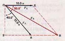
The angle between two forces acting on the same point is often not a right angle. Figure 4-6 represents the vectors for the two forces 10.0 n east and 15.0 n 40.0o east of south acting on point O. The parallelogram is completed as shown. Observe that the diagonal vector representing the resultant is drawn from the point on which the two original forces are acting since the resultant will also act on this point. The magnitude of FR is found graphically to be 23 n. The direction is 30o south of east.
Figure 4-6
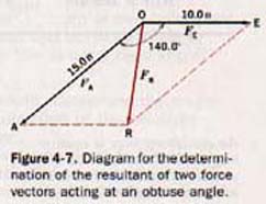
The resultant is very different if the angle between the two forces is 140.0o. The parallelogram is constructed to scale in the same manner. The force vectors are the sides and the angle between them 140.0o. This parallelogram is shown in Figure 4-7. The diagonal must be drawn from O the point at which the two forces act. The graphic solution for FR yields 10 n 8o west of south.
The resultant of two forces acting at an acute or obtuse angle can also be found trigonometrically by means of the law of sines and the law of cosines.
4.3 The Equilibrant Force Equilibrium is the state of a body in which there is no change in its motion. A body in equilibrium is either at rest or moving at constant speed in a straight line.
In this section we shall discuss the conditions for equilibrium of bodies at rest. The same conditions hold for the equilibrium of bodies that are in motion. Examples of these conditions will be discussed in Chapter 5.
A body at rest must be in both translational and rotational equilibrium. The first condition of equilibrium is that there are no unbalanced (net) forces acting on a body. The second condition of equilibrium deals with rotation. It will be discussed in Section 4.12.
When there are no unbalanced forces acting on a body, the vector sum of all the forces acting on the body is zero. For example, if a person pulls on a rope with a force of 80 n and another person pulls on the same rope in the opposite direction with a force of 80 n, the vector sum of the two forces is zero and the system is in equilibrium.
We can say also that each force is the equilibrant of the other. To find the equilibrant of two concurrent forces, we first find their resultant. Then, since the equilibrant must balance the effect of this resultant, it must have the same magnitude but act in the opposite direction.
See Figure 4-8. The equilibrant of three or more concurrent forces can be found in a similar way. First find the resultant by vector addition. Then the equilibrant is graphically drawn from the origin of the forces so that it is equal in magnitude to the resultant but extends in the opposite direction. When two or more forces act concurrently at a paint, the equilibrant force is that single force that if applied at the same point would produce equilibrium.

RESOLUTION OF FORCES
4.4 Components of Force Vectors Frequently a force acts on a body in a direction in which the body cannot move. For example, gravitational force pulls vertically downward on a wagon on an incline, but the wagon can move only along the incline. Finding the magnitude of the force that is pulling the wagon along the incline is an example of resolution of forces.
Instead of a single force, two forces acting together can have the same effect as the original single force. One of the forces can be parallel to the surface of the incline and can pull the wagon along the incline. The other can be perpendicular to the surface of the incline. This force does not contribute to the force along the incline. These forces are at right angles to each other.
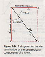
As we saw in Section 2.11, two vectors that have the same effect as a single vector are called the components of the original vector. This procedure of finding component forces is called resolution of forces. See Fig 4-9.
Most of the examples we shall consider involve resolving a force into components that are at right angles to each other.
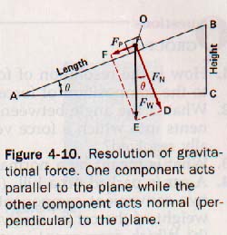
4.5 Resolving Gravitational Forces An object placed on an inclined plane is attracted by the earth. The force of attraction is the weight of the object. See Figure 4-10. The plane prevents the motion of the object in the direction of Fw, the direction in which the earth's attraction acts.
The vector representing the force of attraction may, however, be resolved into two components. One component acts in a direction perpendicular to the surface of the plane. In physics, the term normal is often used to mean perpendicular. Hence we label the normal component FN. The other component, Fp, acts parallel to the plane. We choose these two components because they have physical significance.
The vector FN represents the force exerted by the object perpendicular to the incline or the amount of the object's weight supported by the incline. The vector Fp represents the component that tends to move the object down the incline. (The plane is assumed to be frictionless.) See Figure 4-10.
Using FW as the diagonal, we can construct the parallelogram ODEF and find the relative values of the sides Fp and FN by plotting to scale. We can also express these values trigonometrically.
Since right triangles ABC and OED have mutually perpendicular, or parallel, sides, the triangles are similar.
Making the plane steeper increases the component Fp and decreases the component FN. The vector Fa which is equal and opposite to Fp represents the applied force needed to keep the object from sliding down the plane. The steeper the plane, the greater this force becomes. It should be noted that the normal force that the plane exerts on the object in reaction to force FN is not shown, since it is not involved in the calculations for finding Fa.
FRICTION
4.6 The Nature of Friction In Section 4.5 we discussed the resolution of the weight of an object resting on an incline. One of the components of the weight tends to pull the object down the incline. As the angle of the incline increases, this component also increases. The slightest angle of incline will produce the component that pulls the object down the incline if there is no restraining force on the object.
However, in performing experiments of this type, we find that the object does not begin to slide until the component parallel to the incline reaches a certain value. This means that forces must exist between the object and the incline that prevent the object from sliding. These forces are called forces of friction, or simply friction. Friction is a force that resists motion. It involves objects that are in contact with each other.
The cause of friction is not simple. Some scientists believe that friction is caused mainly by the uneven surfaces of the touching objects. As the surfaces are rubbed together, they tend to interlock and thus offer resistance to being moved over each other. It has been shown that tiny particles are actually torn from one surface and become imbedded in the other.
From this theory of friction one would expect that if the two surfaces are carefully polished, sliding friction between them would be lessened. Experiments have shown, however, that there is a limit to the amount by which friction may be reduced by polishing the surfaces. If they are made very smooth, the friction between them actually increases.
This observation has led to the theory that some cases of sliding friction may be caused by the forces of attraction between the molecules of substances.
In many instances, friction is very desirable. We would be unable to walk if there were no friction behveen the soles of our shoes and the ground. There must be friction between the tires of an automobile and the road before the automobile can move. When we apply the brakes on the automobile, the friction between the brake linings and the brake drums, or disks, slows down the wheels. Friction between the tires and the road brings the car to a stop.
In a less obvious way, friction holds screws and nails in place and it keeps dishes from sliding off a table if the table is not perfectly level. On the other hand, friction can also be a disadvantage, as it is when we try to move a heavy piece of furniture by sliding it across the floor.
4.7 Measuring Friction Friction experiments are not difficult to perform but the results are not always easy to express as equations or laws. The following statements, therefore, should be understood as approximate descriptions only. Furthermore, they deal exclusively with solid objects. Frictional forces involving liquids and gases are beyond the scope of this book.
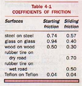
Also, our discussion is restricted to starting and sliding friction. Starting friction is the maximum frictional force between stationary objects. Sliding friction is the frictional force between objects that are sliding with respect to one another.
1. Friction acts parallel to the surfaces that are in contact and in the direction opposite to the motion of the object or to the net force tending to produce such motion.
2. Friction depends on the nature of the materials in contact and the smoothness of their surfaces. The friction between two pieces of wood is different from the friction between wood and metal.
3. Sliding friction is less than or equal to starting friction. Starting friction prevents motion until the surfaces begin to slide. When the object begins to slide, less force is required to keep it sliding than was to start it sliding.
4. Friction is practically independent of the area of contact. The force needed to slide a block along a table is almost the same whether the block lies on its side or on its end. The surfaces are in contact in more places when the area of contact is large, but the pressure is greater when the area is small.
5. Starting or sliding friction is directly proportional to the force pressing the two surfaces together. It does not require as much force to slide an empty chair across the floor as it does to slide the same chair when a person is sitting on it. The reason for this is that the extra force actually deforms the surfaces to some extent and thus increases the friction.
A simple way to measure starting and sliding friction is with a spring balance. Blocks of the same substance, but with different sizes and shapes, are pulled along a smooth surface. If the surfaces in contact are consistently smooth, the ratio between the force of sliding friction and the weight of the block is the same in each trial.
The ratio depends only on the substances used and not on the area of contact or the weight of the block. This ratio is called the coefficient of sliding friction.
It may be defined as the ratio of the force of sliding friction to the normal (perpendicular) force pressing the surfaces together.
4.8 Changing Friction In winter we sand icy sidewalks and streets in order to increase friction. Tire chains and snow tires are used for the same reason. In baseball, pitchers often use rosin to get more friction between their fingers and the ball. Many more examples could be given in which friction is purposely increased by changing the nature of the surfaces that are in contact.
The most common method of reducing sliding friction is by lubrication. A skier applies a layer of wax to the skis to reduce friction. A thin film of oil between rubbing surfaces reduces friction. The lesser friction between a liquid and a solid has replaced the greater friction between two solids.
Alloys have also been developed that are in effect self-lubricating. For example, when steel slides over an alloy of lead and antimony, the coefficient of friction is less than when steel slides over steel. Bearings lined with such an alloy reduce friction. From Table 4-1 it is also obvious that if a bearing is coated with a plastic such as teflon there is very little friction. Such bearings are used in electric motors where the use of a liquid lubricant is undesirable.
Friction may also be greatly reduced through the use of ball bearings or roller bearings. Sliding friction is changed to rolling friction, which has a much lower coefficient. Using steel cylinders to roll a heavy box along the floor is another example of changing sliding to rolling friction.
4.9 Solving Friction Problems The force required to slide an object along a level surface can be computed easily from the weight of the object and the coefficient of sliding friction between the two surfaces. However, when the force applied to the object is not applied in the direction of the motion, it is necessary to resolve forces in the calculation. This resolution of forces is illustrated in the following example. Ah yaz, vectors in action.
PARALLEL FORCES
4.10 Center of Gravity Thus far in our study of forces, we have been treating all the forces acting on a body as if they were acting at a single point. However, there may be many forces, each acting at a different point on the object.
Consider a stone lying on the ground. Since every part of the stone has mass, every part is attracted to the center of the earth. Because of the large size of the earth, all the downward forces exerted on the stone are virtually parallel. The weight of the stone can be thought of as a force vector that is the vector sum, or resultant, of all these parallel force vectors.
Parallel forces act in the same or in opposite directions at different points on an object. The resultant of parallel forces has a magnitude equal to the algebraic sum of all the forces. The resultant acts in the direction of this net force.
But where in the stone is this resultant force acting? Experiments show that if the proper point of application is chosen, the stone can be lifted without producing rotation. The equilibrant lifting force vector is then in line with the resultant (weight) vector of the stone.
In other words, the stone acts as if all its weight were located at one point, which is called the center of gravity. The center of gravity of any object is that point at which all of its weight can be considered to be concentrated. r.
Consider a beam in balance. In this condition the beam is in both translational and rotational equilibrium. This expression means that the beam is not accelerating and its rotation (if any) is uniform.
4.11 Torques The two forces represented in the beam are parallel. They do not act on the same point as did the concurrent forces we studied earlier in this chapter.
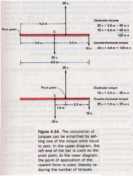
To measure the rotating effect, or torque, of such parallel forces in a given plane, it is first necessary to choose a stationary reference point for the measurements. We shall refer to this stationary reference point as the pivot point.
Sometimes, as in the case of a seesaw, there is a "natural" point about which the rotating effects can be measured. However, such a pivot point is "natural" only when the seesaw is in motion. When it is motionless there is no "natural" pivot point. Any point on the seesaw, or even beyond it, may be chosen.
Once a suitable pivot point is chosen, a perpendicular line is drawn on the vector diagram from it to each of the lines along which force vectors act on the object.
Each such line is called a torque arm. In some cases, the force vectors must be extended in order to meet the perpendicular. Torque, T, is the product of a force and the length af its torque arm. The unit of torque is the meter-newton.
To identify a torque as clockwise or counterclockwise, imagine that the beam is free to rotate around a stationary pivot point. Further imagine that the force producing the torque is the only force acting on the beam. The direction in which the beam would rotate is the direction of the torque.
4.12 Rotational Equilibrium In Section 4.3 we discussed the conditions necessary for the translational equilibrium of an object. These conditions, however, do not prevent the rotary motion of an object that is subjected to torques.
To prevent rotation in a given plane a second condition of equilibrium must be met.
The second condition of equilibrium in a given plane is that the sum of all the clockwise torques equals the sum of all the counterclockwise torques about any pivot point.
4.13 Coupled Forces The conditions of equilibrium hold true no matter how many forces are involved. An interesting example is one in which two forces of equal magnitude act in opposite directions in the same plane, but not same point. Such a pair of forces is called a couple.
A good example of a couple is the pair of forces acting on the opposite poles of a compass needle when the needle is not pointing north and south.
A couple cannot be balanced by a single force since this single force would be unbalanced and would produce linear motion where it was applied. The only way to balance a couple is with another couple; the torques of the two couples must have equal magnitudes but opposite directions.
Solving problems of equilibrium:
The clockwise torques must equal the counterclockwise torques.
The total of upward forces must be equal to the total of downward forces.
SUMMARY
Forces are vector quantities. A net force will change the state of motion of an object. Forces can be exerted over long distances. Every force is opposed by an equal and opposite force.
A resultant force is a single force that produces the same effect as several forces acting along lines that pass through the same point. The equilibrant force is the single force that produces equilibrium when applied at a point at which two or more concurrent forces are acting.
A single force may be resolved into two components, usually acting at right angles to each other. Resultant and component forces are found by the parallelogram method.
Friction is a force that resists the motion of objects that are in contact with each other. It acts parallel to the surfaces that are in contact, depends on the nature and smoothness of the surfaces, is independent of the area of contact, and is directly proportional to the force pressing the surfaces together. Starting friction is usually greater than sliding friction. The coefficient of friction is the ratio of the force of friction to the perpendicular force pressing the surfaces together.
Parallel forces act in the same or in opposite direction. The center of gravity of an object is that point at which all the object's weight can be considered be concentrated.
A stationary object is in translational and rotational equilibrium. The torque produced by a force is the product of the force and the length of torque arm on which it acts.
To produce equilibrium in parallel forces, the sums the forces in opposite directions must be equal and the sum of all the clockwise torques must equal the sum of all the counterclockwise torques about a pivot point. Two forces of equal magnitude act in opposite directions but not along the same line are called a couple.
VOCABULARY
center of gravity, coefficient of sliding friction, concurrent forces, couple, equilibrant force, equilibrium, friction, parallel forces, resolution of forces, resultant force, rotational equilibrium, torque, torque arm, translational equilibrium.
Ah Yaz Indeed!
 Assignment Sheet for this Research Text Only.
 Go to Textbook Assignments for Portfolio:
.................................First Semester
.................................Second Semester