Magnetic Effects
Magnetic Effects
The purpose of this is to give quick reference to information or to use in an emergency (like if your text has accidentally been left under your desk at school).
This is NOT intended to replace reading the text with its excellent photographs, diagrams, charts, and tables.
MAGNETISM
19.1 Magnetic Materials Physicists believe that all magnetic phenomena result from forces between electric charges in motion. Vast quantities of electric energy are now generated as a consequence of relative motion between electric conductors and magnetic fields. Electric energy is transformed into mechanical energy by relative motion between electric currents and magnetic fields. The function of many electric measuring instruments depends on the relationship between electricity and magnetism. The basic theory of electric generators and motors is presented in Chapter 20.
Electric measuring instruments are discussed later in this chapter. Before undertaking the study of magnetic effects of electric currents, we shall examine the magnetic properties of substances and learn of the nature of magnetism and magnetic fields. Deposits of a magnetic iron ore were discovered many centuries ago by the Greeks in a section of Turkey. The region was then known as Magnesia and the ore was called magnetite. Deposits of magnetite are found in the Adirondack Mountains of New York and in other regions of the world.
Pieces of magnetite are known as natural magnets. A suspended piece of magnetite aligns itself with the magnetic field of the earth. These natural magnets, known as lodestones (leading stones), were first used as magnetic compasses during the twelfth century. A few materials, notably iron and steel, are strongly attracted by magnets; cobalt and nickel are attracted to a lesser degree. These substances are said to have ferromagnetic properties.
Special alloys such as permalloy and alnico have extraordinary ferromagnetic properties. Physicists have shown much interest in the structure of materials possessing the property of ferromagnetism.
Today very strong magnets are made from ferromagnetic substances. Alnico magnets may support a weight of over 1000 times that of the magnets themselves. Ferromagnetic substances are commonly referred to simply as "magnetic substances." Materials are commonly classified as magnetic or nonmagnetic.
Those that do not demonstrate the strong ferromagnetism of the Iron Family of metals are said to be "nonmagnetic." However, if these materials are placed in the field of a very strong magnet, some are observed to be slightly repelled by the magnet while others are very slightly attracted.
Zinc, bismuth, sodium chloride, gold, and mercury are a few of the substances that are feebly repelled; they are diamagnetic. The property of diamagnetism is an important concept in the modern theory of magnetism, as we shall see in Section 19.2.
Wood, aluminum, platinum, oxygen, and copper(II) sulfate are examples of substances that are very slightly attracted by a strong magnet. Such materials are paramagnetic, and this magnetic behavior is called paramagnetism.
19.2 The Domain Theory of Magnetism William Gilbert's report on his experiments with natural magnets, published in 1600, probably represents the first scientific study of magnetism. In the years that followed, discoveries by Coulomb, Oersted, and Ampere added to our knowledge of the behavior of magnets and the nature of magnetic forces.
Physicists believe, however, that it is only within this century that they have begun to understand the true nature of magnetism. The present view is that the magnetic properties of matter are electric in origin and result from the movements of electrons within the atoms of substances.
Since the electron is an electrically charged particle, this theory suggests that magnetism is a property of a charge in motion. If so, we can account for the energy associated with magnetic forces by using known laws of physics.
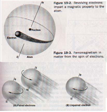
Two kinds of electron motion are important in this modern concept of magnetism. First, an electron revolving about the nucleus of an atom imparts a magnetic property to the atom structure. See Figure 19-2.
When the atoms of a substance are subjected to the magnetic force of a strong magnet, the force affects this magnetic property, opposing the motion of the electrons. The atoms are thus repelled by the magnet. This is diamagnetism. If the electron's only motion were its movement about the nucleus, all substances would be diamagnetic.
Diamagnetic repulsion is quite feeble in its action on the total mass of a substance. The second kind of motion is that of the electron spinning on its own, axis. Each spinning electron acts as a tiny permanent magnet. Opposite spins are designated as + and - spins; electrons spinning in opposite directions tend to form pairs and so neutralize their magnetic character. See Figure 19-3 (above). The magnetic character of an atom as a whole may be weak because of the mutual interaction between the electron spins.
Magnetic properties are associated with both kinds of electron motion. The atoms of some substances may possess permanent magnet characteristics because of an imbalance between orbits and spins. These atoms act like tiny magnets, called dipoles, and are attracted by strong magnets.
Substances in which this attractive effect exceeds the diamagnetism common to all atoms show the property of paramagnetism.
In the atoms of ferromagnetic substances there are unpaired electrons whose spins are oriented in the same way. The common metals iron, cobalt, and nickel and the rare earth elements gadolinium and dysprosium show strong ferromagnetic properties.
Some alloys of these and other elements, as well as certain metallic oxides called ferrites, also exhibit strong ferromagnetic properties. The inner quantum levels, or shells, of the atom structures of most elements contain only paired electrons. The highest quantum level, or outer shell, of each of the noble gases (except helium) consists of a stable octet of electrons made up of four electron pairs.
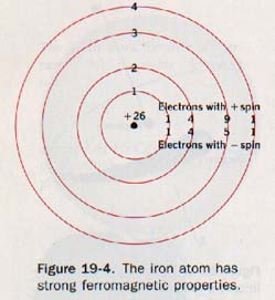
The atoms of other elements achieve this stable configuration by forming chemical bonds. Only in certain transition elements that have incomplete inner shells do unpaired electrons result in ferromagnetic properties. The electron configuration of the iron atom, Figure 19-4, shows four unpaired electrons in the third principal quantum level. The similarly oriented spins of these electrons, enhanced by the influence of nearby atoms in the metallic crystal, account for iron's strong ferromagnetism.
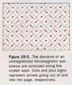
From the preceding discussion, it would seem that every piece of iron should behave as a magnet. However, such is not the case. Atoms are grouped in microscopic magnetic regions called domains. The atoms in each domain are magnetically polarized parallel to a crystal axis. In a polycrystalline specimen, ordinarily these axes (and the domains) are oriented in all possible directions. The domains effectively cancel one another and the net magnetism is essentially zero. In Figure 19-5 the polarity of each domain in an unmagnetized material is represented by an arrow.
When a ferromagnetic material is placed in an external magnetic field, two effects occur. The domains more favorably oriented in this magnetic field may increase in size at the expense of less favorably oriented adjacent domains. Other domains may rotate in order to become more favorably oriented with respect to the external field. The material becomes magnetized.
If the domain boundaries remain extended to some degree even after the external magnetizing force is removed, the material is said to be "permanently" magnetized.
When the direction of magnetization of a magnetic domain is rotated by an external magnetic field, it must be understood that the material of the domain does not change its position in the specimen. It is only its direction of magnetization that changes.
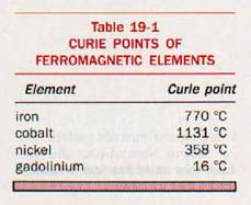
When the temperature of a ferromagnetic material is raised above a certain critical value, the domain regions disappear and the material becomes paramagnetic. This temperature is known as the Curie point. It is usually lower than the melting point of the substance. The Curie points for some ferromagnetic substances are given in Table 19-1.
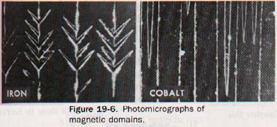
When a single crystal of iron is sprinkled with colloidal particles of iron oxide, the microscopic domains become visible. Using this technique, physicists are able to photograph magnetic domains and observe the effects of external magnetic fields on them.
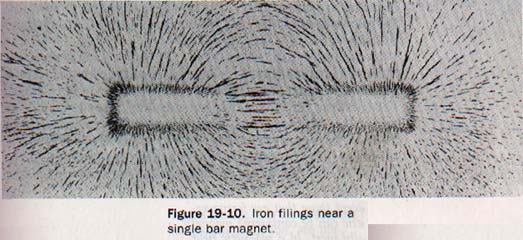
19.3 Force Between Magnet Poles The fact that iron filings cling mainly to the ends of a bar magnet indicates that the magnetic force acts on the filings primarily in these regions, or poles; it does not mean that the middle region of the magnet is unmagnetized.
The pole that points toward the north when the magnet is free to swing about a vertical axis is commonly called the north-seeking pole, or N pole.
The opposite pole, which points toward the south, is called the south-seeking pole, or S pole.
Suppose a bar magnet is suspended as shown in Figure 19-7.
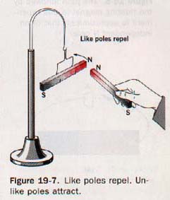
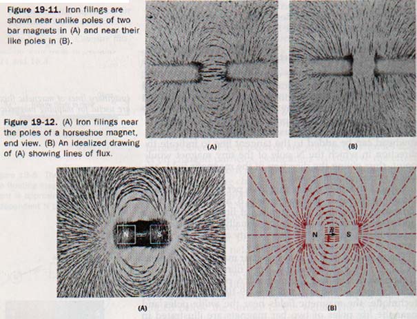
When the N pole of a second magnet is brought near the N pole of the suspended magnet, the two repel each other. A similar action is observed with the two S poles. When the S pole of one magnet is placed near the N pole of the other magnet, they attract each other. Such experiments show that like poles repel and unlike poles attract.
Magnets usually have two well-defined poles-- one N and one S. Sometimes long bar magnets acquire more than two poles, and an iron ring may have no poles at all when magnetized. Physicists have long speculated about the existence of single-pole magnetic particles called monopoles. Known magnetic poles, however, always come in pairs called dipoles. The most elementary magnet has an S pole and an N pole. If cut in half, each half is found to be dipolar. A magnet has an S pole for every N pole.
The first quantitative study of the force between two magnetic poles is generally credited to Coulomb. He found this magnetic force governed by the same inverse square relationship that applies to gravitational force and electrostatic force.
Coulomb's law of magnetism is: The force between two magnetic poles is directly proportional to the product of the strengths of the poles and inversely proportional to the square of the distance between them. The force is one of repulsion or attraction, depending on whether the magnetic poles are alike or different.
19.4 Magnetic Fields of Force In Section 16.9 we described the electric field of force near an electrically charged object. Electric forces are not the only forces that act on charged particles. Sometimes we observe the effect of a force that is both perpendicular and proportional to the velocity of a moving charge. This force identifies a magnetic field.
A dipole magnet in such a region of space experiences a torque. We speak of a magnetic field in the space around a bar magnet in the same way we speak of an electric field around a charged rod. Furthermore, we can represent a magnetic field by lines of flux, just as we represented an electric field by lines of force.
The behavior of our imaginary independent N pole in a magnetic field can be approximated by using a magnetized darning needle as illustrated in Figure 19-8.
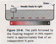
The needle is supported by cork so that it floats with the N pole extended below the surface of the water. The S pole is far enough removed to have negligible influence on the movement of the needle. A bar magnet placed under the glass dish with its N pole near the needle causes the floating magnet to move along a path that approximates the path an isolated N pole would follow.
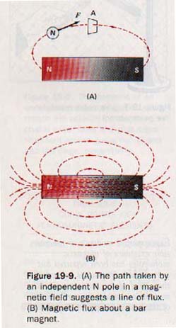
The path of an independent N pole in a magnetic field suggests a line of flux. A line of flux is a line so drawn that a tangent to it at any point indicates the direction of the magnetic field. Flux lines are assumed to emerge from a magnet at the N pole and to enter the magnet at the S pole. Every flux line is a closed path running from S pole to N pole within the magnet. See Figure 19-9.
The lines of flux perpendicular to a specified area in the magnetic field are collectively called the magnetic flux, for which the Greek letter phi, φ, is used. The unit of magnetic flux is the weber (wb).
The magnetic flux density, B, is the number of flux lines per unit area that permeates the magnetic field. The flux density B is a vector quantity; the direction of B at any point in the magnetic field is the direction of the field at that point.
Flux density is expressed in webers per square meter (wb/m2). The flux density determines the magnetizing force at any point in the magnetic field. The weber per meter2 is also called the tesla.
1 weber/meter2 = 1 tesla
19.5 Magnetic Permeability In Section 19.4 we described the effect of a magnetic field of force on iron filings and on a magnetized needle as experienced through glass and water.
Nonmagnetic materials in general are transparent to magnetic flux; that is, their effect on the lines of flux is not appreciably different than that of air. The property of a material by which it changes the flux density in a magnetic field from the value in air is called its permeability.
Permeability is a ratio of flux densities and is without dimension. The permeability of empty space is taken as unity and that of air as very nearly the same.
The permeabilities of diamagnetic substances are slightly less than unity; permeabilities of paramagnetic substances are slightly greater than unity. Permeabilities of ferromagnetic materials are many times that of air.
If a sheet of iron covers a magnet, there is little magnetic field above the sheet. The flux enters the iron and follows a path within the iron itself. Similarly, an iron ring placed between the poles bf a magnet provides a better path than air for the magnetic flux. This effect is illustrated in Figure 19-13. The flux density in iron is greater than it is in air; therefore, iron is said to have a high permeability. The permeabilities of other ferromagnetic substances are also very high.
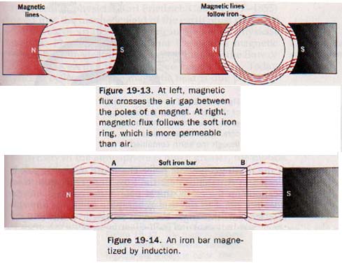
Suppose a bar of soft iron lies in a magnetic field, as in Figure 19-14. Because of the high permeability of the iron, the field is distorted and the magnetic flux passes through the iron in preference to the air. Under these circumstances the soft iron bar becomes a magnet with end A as the S pole and end B as the N pole. Such a bar is said to be magnetized by induction. Magnetism produced in a ferromagnetic substance by the influence of a magnetic field is called induced magnetism.
If the magnetic field is removed by withdrawing the two bar magnets, most of the induced magnetism will be lost. Magnets produced by induction are known as temporary magnets.
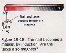
A piece of hardened steel is not so strongly magnetized by induction but retains a greater residual magnetism when removed from the induction field. There is no significant difference in the process if the iron bar in Figure l9-14 is brought into contact with one of the magnet poles. The magnetization process is somewhat more efficient due to the reduction of the air gap. See Figure 19-15.
19.6 Terrestrial Magnetism Suppose the earth contained a great bar magnet. See Figure 19-16. It would produce a magnetic field similar to its actual field. Over most of the earth's populated surface the north-seeking pole of a compass points northward. Although it is the south pole of our fictitious magnet that attracts the N pole of the compass, the pole region is conventionally called the north magnetic pole because it is located in the northern hemisphere. Similarly, the pole region in the southern hemisphere is called the south magnetic pole.
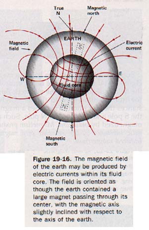
The earth's magnetic axis does not coincide with its polar (geographic) axis, but is inclined to the polar axis at a small angle. The north magnetic pole, at latitude 73oN and longitude 100oW, is about 2000 km south of the north geographic pole. The south magnetic pole is located in Antarctica near the Ross Sea. Thus from most locations on the earth, the N pole of the compass needle does not point to the true geographic north.
At any surface location the angle between magnetic north and the true north is called the declination, or variation.
A compass needle mounted on a horizontal axis and provided with a means of measuring the angle the needle makes with the horizontal plane is called a dipping needle.
At certain places on the earth's surface, about midway between the magnetic poles, the angle of dip is zero and the needle is horizontal. A line drawn through a succession of such points identifies the magnetic equator. The angle of dip is 90o at the magnetic pole. The dip, or deviation between the equilibrium position of a dipping needle and the horizontal, is known as the magnetic inclination.
In 1600 the English physicist William Gilbert (1540-1603) published his scientific treatise De magnete, which deals with the magnetism of the earth. This is one of the earliest publications on the experimental treatment of a scientific topic. Gilbert inferred that the earth behaved as a large magnet because the interior consisted of permanently magnetic material. Today scientists believe the core of the earth is too hot to be a permanent magnet and is fluid rather than solid.
The German physicist Karl Friedrich Gauss (1777-1855) showed that the magnetic field of the earth must originate inside the earth. In 1939 the American theoretical physicist Walter M. Elsasser suggested that the earth's magnetic field results from electric currents generated by the flow of matter in the earth's fluid core. Today physicists believe that the magnetic field is due primarily to electric currents within the earth. They may becaused by the convection currents that cause continental drift.
19.7 The Magnetosphere Because space vehicles now travel to the outer limits of the earth's atmosphere and beyond, there is a growing interest in a region of the outer atmosphere known as the magnetosphere. Located beyond 200 km, the magnetosphere is the region in which the motion of charged particles is governed primarily by the magnetic field of the earth. At lower altitudes, where the density of the atmosphere is much greater, the motion of charged particles is controlled largely by collisions. The magnetosphere on the side facing the sun extends beyond the earth's surface approximately 57,000 km, or about 10 earth radii.
On the side away from the sun, the magnetosphere probably extends outward for hundreds of earth radii. The elongated shape results from the influence of the onrushing solar wind, or solar plasma. The solar wind, consisting mainly of protons and electrons emitted by the sun, compresses the magnetosphere on the side nearest the sun.
ELECTROMAGNETISM
19.8 The Link Between an Electric Current and Magnetism It It can easily demonstrated that electrostatic charges and stationary magnets have no effect on one another.
However, in 1820 Hans Christian Oersted (er-stet) (1777-1851), a Danish physicist and professor of physics at the University of Copenhagen, observed that a small compass needle is deflected when brought near a conductor carrying an electric current.
This was the first evidence of a long-suspected link between electricity and magnetism. Oersted discovered that forces exist between a magnet and electric charges in motion. His famous experiment is so significant that a brief description of it is in order.
A dry cell, compass, switch, and conducting wire are arranged as shown in Figure 19-19(A).
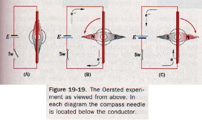
With the switch open, a straight section of the conductor is supported above the compass in the vertical plane of the compass needle. In Figure 19-19(B) the dry-cell connection is such that the electron flow will be from north to south. When the switch is closed, the N pole of the compass is deflected toward the west. When the dry-cell connections are reversed so electron flow is from south to north, the N pole of the compass is deflected to the east, as in Figure 1919(C). It is evident that a magnetic field exists in the region near the conductor when the circuit is closed. Furthermore, the direction of the field is dependent on the direction of the current in the conductor.
If the experiment is repeated with the conductor placed below the compass needle, the compass deflection is opposite to that in the first experiment, This suggests, but does not prove, that the magnetic field encircles the conductor.
19.9 Magnetic Field and a Charge in Motion Shortly after Oersted's discovery, the French physicist Ampere determined the shape of the magnetic field about a conductor carrying a current. He had discovered that forces exist between two parallel conductors in an electric circuit. If the two currents are in the same direction, the force is one of attraction; the force is one of repulsion if the currents are in opposite directions. See Figure 19-21.
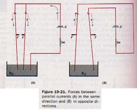
The ampere is the current flow of 1 coulomb per second.
The Left Hand Rule for electromagnets: Grasp the conductor in the left hand with the thumb extended in the direction of the electron current. The fingers then will circle the conductor in the direction of the magnetic field (N to S).
Solenoids (coils): When wrapping the wire into a coil, the magnetic lines are added together loop by loop.
The Left Hand Rule for Coils: Grasp the coil with the left hand with the fingers pointed in the direction of the current, - to +, and the thumb will point to the N-magnetic pole of the coil.
19.21 The Electromagnet A solenoid with a core of air, wood, or some other nonmagnetic material does not produce very strong electromagnet because the permeability all nonmagnetic substances is essentially equal to that of air-- unity. Substitution of such materials for air does not noticeably change the flux density.
Soft iron, on the other hand, has a high permeability. If an iron rod is substituted for air as the core material, the density is greatly increased. Strong electromagnets therefore have ferromagnetic cores with high permeability. For a given core material, the strength of the electromagnet depends on the magnitude of the current and the of turns. In other words, its strength is determined by the number of ampere-turns.
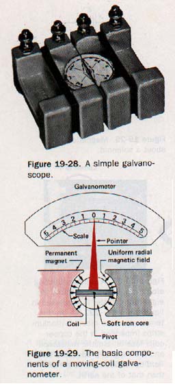
19.12 The Galvanometer Suppose we form a wire loop in a vertical plane, place a compass needle (free to rotate in horizontal plane) in the center of it, and then introduce a current into the loop. The needle will be deflected. If we increase the number of turns sufficiently, even a feeble current will produce a deflection of the needle.
Such a device is called a galvanoscope, may be used to detect the presence of an electric current or to determine its direction. A simple galvanoscope is shown in Figure 19-28.
A more versatile instrument for detecting feeble currents is the galvanometer, the essential parts of which are in Figure 19-29.
29.13 The d-c Voltmeter The potential difference across a galvanometer is quite small even when the needle is fully deflected. If a galvanometer is to be used to measure voltages of ordinary magnitudes, we must convert it to a high-resistance instrument. The essential parts of a d-c voltmeter are shown in Figure 19-31.
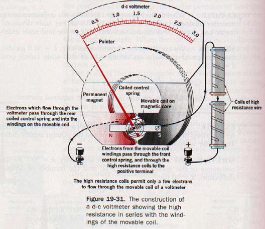
If a high resistance is added in series with the moving coil, most of the potential drop appears across this series resistor, or multiplier. Since a voltmeter is connected in parallel with the part of a circuit across which the potential difference is to be measured, a high resistance prevents an appreciable loading effect. By the proper choice of resistance, the meter can be calibrated to read any desired voltage.
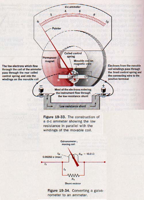
19.14 The d-c Ammeter We could use the basic galvanometer in Section 19.12 as a microammeter by calibrating the graduated scale to read directly in microamperes. However, the meter would not be useful in circuits in which the current exceeded 2500 microamperes.
Current in the resistance of a galvanometer coil produces I2R heating, and an excessive current would burn out the meter. To convert the galvanometer to read larger currents, an alternate (parallel) low-resistance path for current, called a shunt, must be provided across the terminals. By the proper choice of shunt resistance, we can calibrate the meter to read over the required range of current magnitudes. See Figure 19-33.
19.34 The Ohmmeter An ohmmeter measures the current in a circuit provided by a built-in battery. The ammeter is calibrated in ohms. The more current, the less is the resistance being measured.
SUMMARY
Magnetite, a magnetic iron ore, is a natural magnet. Metals of the Iron Family and special metallic alloys and oxides are strongly attracted by magnets; they have ferromagnetic properties. Very strong magnets are made from ferromagnetic substances. Materials that are not ferromagnetic are commonly said to be nonmagnetic. Ferromagnetic materials have high permeabilities. Nonmagnetic materials in general are transparent to magnetic flux. These materials may be very feebly diamagnetic or paramagnetic.
Magnetism is explained by the domain theory. Coulomb's law for magnetism is a quantitative expression for the force acting between two magnetic poles. A magnetic field, and its influence on a fictitious N pole, shows similarities to an electric field and its influence on a positive test charge.
A charge in motion is surrounded by a magnetic field. The core of a coil carrying an electric current becomes a magnet. Strong electromagnets are produced by winding a conducting coil around a ferromagnetic core. The strength of an electromagnet depends on the number of turns of coil and the magnitude of the current in the coil.
The galvanometer is the basic meter for d-c measurements. The galvanometer can be calibrated as a voltmeter by placing a high resistance in series with the galvanometer coil. It can be calibrated as an ammeter by placing a very low resistance shunt across the galvanometer coil.
An ohmmeter requires a source of emf, an adjustable resistance, and a sensitive ammeter. It is essentially a voltmeter-ammeter method of measuring the resistance of a circuit component.
VOCABULARY
ammeter, left hand rules, Coulomb's law of magnetism, Curie point, declination, diamagnetism, dipping needle, electron pair, ferromagnetism, flux density, galvanometer, induced magnetism, line of flux, magnetic domain, magnetic induction, magnetosphere, ohmmeter, paramagnetism. permeability, solar wind, solenoid, voltmeter.
Ah Yaz Indeed!
 Assignment Sheet for this Research Text Only.
 Go to Textbook Assignments for Portfolio:
.................................First Semester
.................................Second Semester