Direct-Current Circuits
Direct-Current Circuits
The purpose of this is to give quick reference to information or to use in an emergency (like if your text has accidentally been left under your desk at school).
This is NOT intended to replace reading the text with its excellent photographs, diagrams, charts, and tables.
SOURCES OF DIRECT CURRENT
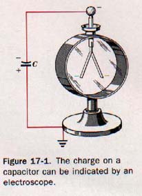
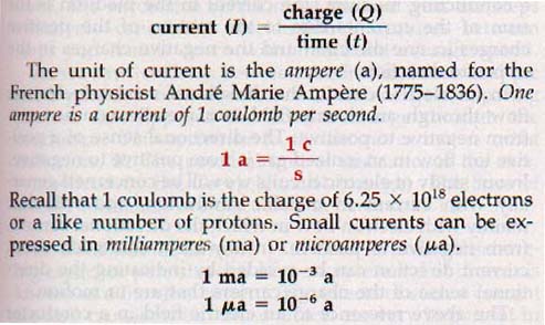
17.1 Electric Charges in Motion The quantity of charge on a capacitor is indicated by the potential difference between the plates.
Q = CV
If the capacitance, C, for a given capacitor is a constant, then the charge, Q, is proportional to the potential difference, V, across it.
A potential difference across a charged capacitor, and therefore a charge on the capacitor, can be indicated by an electroscope connected across the capacitor plates. See Figure 17-1.
Suppose the two plates of the capacitor are now connected by a heavy copper wire as in Figure 17-2(A). The leaves of the electroscope immediately collapse, indicating that the capacitor has been discharged rapidly. Free electrons flow from the negative plate of the capacitor and from the electroscope through the copper wire to the positive plate. This action quickly establishes the normal distribution of electrons characteristic of an uncharged capacitor.
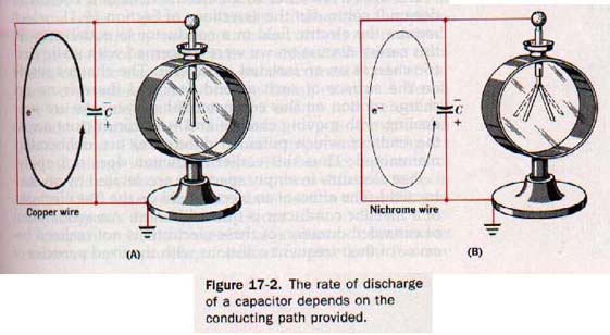
Considering the charged capacitor of Figure 17-1 again, suppose the plates are connected by means of a long, fine wire made of nichrome, which has few free electrons compared with copper. The leaves of the electroscope collapse more gradually than before. See Figure 17-2(B).
This delay means that a longer time is required to discharge the capacitor completely. When any conductor connects the plates of the capacitor, electrons move from the negative plate through the conductor to the positive plate. This transfer decreases the charge on each plate and the difference of potential between the plates.
The charge, Q, on either plate of a capacitor is proportional to the potential difference, V, between the plates. The rate at which the charge decreases, in c/s, is proportional to the rate at which the potential difference decreases, in v/s. Now, the rate of decrease of charge on the capacitor must represent the rate of flow of the charge, in c/s, through the conductor. Thus the rate at which the leaves of the electroscope collapse indicates the rate of flow of the charge through the conductor. During the time the capacitor is discharging, a current is said to exist in the conducting wire. An electric current, I, in a conductor is the rate of flow of charge through a cross section of the conductor.
17.2 Continuous Current The current from a discharging capacitor persists for a very short interval of time, it is known as a transient current. The effects of such a current are also transient, but those effects are very important in certain types of electronic circuits. In the general applications of electricity, more continuous currents are required. The effects of current electricity are quite different from those of static electricity. The electric current is one of our most convenient means of transferring energy.
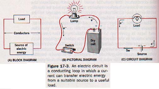
A closed loop conducting path is needed if energy is to be utilized outside the source; this conducting loop is known as an electric circuit. The device or circuit component utilizing the electric energy is called the load.
The basic components of an electric circuit are illustrated in three different ways in Figure 17-3.
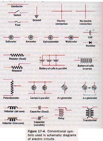
Conventional symbols used in schematic (circuit) diagrams are shown in Figure 17-4.
A capacitor would be useful as a source of continuous current over a prolonged period of time only if some means were available for keeping it continuously charged. We would need to supply electrons to the negative plate of the capacitor as rapidly as they were removed by the current in the conducting loop. Similarly, we would need to remove electrons from the positive plate of the capacitor as rapidly as they were deposited by the current.
What is needed is some kind of "electron pump." Several practical energy sources are available to maintain a difference of potential across an operating electric circuit.
17.3 Sources of Continuous Current The transformation of available energy into electric energy is accomplished by one of two basic methods: dynamic conversion or direct conversion. Dynamic converters are rotating machines, and it is these machines that supply most of our requirements for electric energy today. Direct conversion methods produce energy transformations without moving parts. We shall consider the following sources of continuous current:
1. Electromagnetic. The major source of electric current in practical circuits today depends on the principle of electromagnetic induction. If a conducting loop is rotated in a magnetic field, the free electrons of the conductor are forced to move around the loop and thus constitute a current. This is the basic operating principle of electric generators. It is an example of the transformation of mechanical energy into electric energy, a dynamic conversion process. Electromagnetic induction and the electric generator are discussed in Chapter 20.
2. Photoelectric. The photoelectric effect was first observed by Heinrich Hertz. He noticed that a spark discharge occurred more readily when charged metal spheres were illuminated by another spark discharge. Electrons are emitted from the surface of a metal illuminated by light of sufficiently short wavelength.
The alkali metals are photosensitive to light in the near ultraviolet region of the radiation spectrum. Two of these metals, potassium and cesium, emit photoelectrons when exposed to ordinary visible light. In the case of most metals, the incident light for photoemission corresponds to radiations deep in the ultraviolet region.
When a photon of the incident light is absorbed by the metal, its energy is then transferred to an electron. If the motion of this electron is toward the surface and its energy at the surface is sufficient to overcome the forces that bind it within the surface of the metal, it is emitted as a photoelectron.
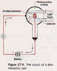
If properly isolated, the metal surface acquires a positive charge as photoelectrons are emitted. As the charge increases, other electrons are prevented from escaping from the metal and the action stops. If, however, the metal is placed in an evacuated tube and made part of a circuit, as in Figure 17-5, it can act as a source of current whenever light is incident upon its surface. The metal thus serves as the electron pump mentioned in Section 17.2. The evacu• ated tube containing the metallic emitter is called a photoelectric cell.
The photoelectric cell shown in Figure 17-5 has a coating of potassium metal deposited on the inner surface of a glass tube, leaving an aperture through which light can enter. A metallic ring near the focus of the emitter surface acts as a collector of photoelectrons. The emitter is connected externally to the negative terminal of a battery, and the collector is connected to the positive terminal.
The collector is thus maintained at a positive potential with respect to the emitter. The force of the resulting electric field acts on the emitted electrons, driving them to the collector. The small photoelectron current can thus be maintained in the external circuit as long as light photons are incident on the emitter surface. A galvanometer, an electric meter sensitive to very feeble currents, can be placed in the circuit to indicate the relative magnitude and direction of the current.
A bright light of effective frequency causes the ejection of many electrons from the surface of the photosensitive metal, while light of the same frequency but of a lower intensity produces fewer photoelectrons. Thus the current produced by the photoelectric cell is determined by the intensity of the incident light; this is a case in which radiant energy is transformed into electric energy. Some form of photosensitive cell is used in devices that are controlled or operated by light.
3. Thermoelectric. Suppose we form a conducting loop circuit that consists of a length of iron wire, a length of copper wire, and a sensitive galvanometer, as shown in Figure 17-6. One copper-iron junction is put in a beaker of ice and water to maintain a low temperature; the other junction is heated by a gas flame. As the second junction is heated, the galvanometer indicates a current in the loop. An electric circuit incorporating such junctions is known as a thermocouple.
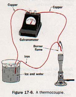
The magnitude of the current is related to the nature of the two metals forming the junctions and the temperature difference between the junctions. A thermocouple can be used as a sensitive thermometer to measure radiant energy. The iron-copper junction is useful for temperatures up to about 275 oC.
Since heat energy is transformed directly into electric energy, the thermocouple is a thermoelectric source of current. If a sensitive galvanometer is properly calibrated; temperatures can be read directly.
The hot junction of the thermocouple can be placed in a remote location where it would be impossible to read an ordinary thermometer. Ah, Navy refrigerators, steel mill furnaces.
The heating effect of an electric current in the resistance of a conductor is an irreversible phenomenon. On the other hand, the basic thermoelectric effects discussed in this section are reversible.
The best known of these effects is described in this section: when the junctions of two dissimilar metals are subjected to a difference in temperature, a current is set up in the loop, known as the Seebeck effect, it is named after its discoverer who first observed the phenomenon in 1821. See Figure 17-7(A).
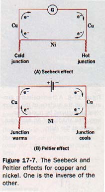
The Peltier effect is produced when a direct current is passed through a junction formed by two dissimilar metals. The junction becomes warmer or cooler depending on the direction of the current, as shown in Figure 17-7(8).
4. Piezoelectric. When Certain crystals, such as Rochelle salt and quartz, are subjected to a mechanical stress, the opposite surfaces will become electrically charged. The difference of potential between the stressed surfaces is proportional to the amount of stress applied to the crystal. Reversing the stress reverses the charges also. If the crystal is suitably supported and a conducting circuit is connected between surfaces having a difference of potential, electricity will flow through the circuit.
Thus mechanical energy is transformed into electric energy. This transformation is known as the piezoelectric effect, and the crystal with its supporting mechanism is called a piezoelectric cell.
Crystal microphones use the piezoelectric effect to transform the alternating pressure of sound waves into an electric current that varies as the pressure of the sound waves varies. A crystal phonograph pickup responds in a similar manner to the varying stress caused by the needle riding in the groove of the record.
The piezoelectric effect is reversible; that is, the crystal experiences a mechanical strain when subjected to an electric stress. An alternating difference of potential properly placed across the crystal will cause mechanical vibrations proportional to the variations of the voltage. Crystal headphones use this reciprocal effect. Beepers, too.
5. Chemical. There are certain chemical reactions that involve a transfer of electrons from one reactant to the other. The reactions that occur spontaneously (that is, of and by themselves) can be used as sources of continuous current.
During the chemical reaction, electrons are removed from one reactant. A like number of electrons is added to the other reactant. If the reactants are separated in a conducting environment, the transfer of electrons will take place through an external circuit connecting the reactants.
This electron transfer will continue for as long as reactants are available. Such an arrangement is known as an electrochemical cell.
Chemical energy is transformed into electric energy during the chemical reaction. Electrochemical cells include primary, storage, and fuel cells. A primary cell, a flashlight cell for example, is ordinarily replaced when its reactants are used up. Storage cells, as in an automobile battery, are reversible.
Electric energy is initially stored as chemical energy, and the cell can be repeatedly "recharged" with energy. If the reactants in a primary cell are supplied continuously, the arrangement is called a fuel cell. Fuel cells have been used as the source of electric current in spacecraft.
37.4 The Dry Cell The essential components of a primary cell are an electrolyte and two electrodes of unlike materials, one of which reacts chemically with the electrolyte.
Let us examine the carbon-zinc dry cell as a common example of the primary cell. A cut-away diagram of this cell is shown in Figure 17-9. The electrolyte is a moist paste of ammonium chloride. One electrode is a carbon rod. The MnO2 and other electrode, a zinc cup is consumed as the cell is used.
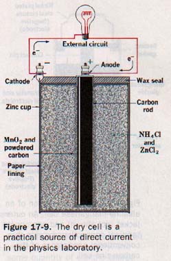
When an external circuit is connected across the cell, zinc atoms react with the electrolyte and lose electrons, which remain with the zinc cup. This reaction leaves the zinc electrode negatively charged.
We shall refer to the negative electrode as the cathode. It is the electron rich electrode.
Simultaneously, the electrolyte removes a like number of electrons from the carbon electrode. This reaction leaves the carbon electrode positively charged. We shall call the positive electrode the anode. It is the electron-poor electrode.
The electrons move through the external circuit from cathode to anode because of the difference in potential between the electrodes. Thus the cell acts as a kind of electron pump. It removes electrons with low potential energy from the anode and supplies electrons with high potential energy to the cathode while current is in the external circuit.
Electrons flow through the external circuit from cathode to anode. This unidirectional current is an example of direct current, dc, If we open the circuit and stop the current, the maximum potential difference is quickly established across the cell. The magnitude of this open-circuit potential difference is dependent solely on the materials that make up the electrodes. For the carbon-zinc cell it is about 1.5 volts.
The open circuit potential difference can be referred to as the emf, or electromotive force, of the cell. The symbol for emf is E and the unit is the volt (v). The cell itself must supply a definite amount of energy for each unit of charge that is stored on either electrode; the emf of a source is the energy per unit charge supplied by the source.
Thus the potential difference across the cell on an open circuit is equal to the emf of the cell.
As shown in Section 17.6, the potential difference, V, across a source of emf on a closed circuit is less than the emf, E
17.5 Combinations of Cells Energy-consuming devices that form the loads of electric circuits are designed to draw the proper current for their operation when a specific potential difference exists across their terminals. For example, a lamp designed for use in a 6-volt electric system of an automobile would draw an excessive current and burn out if placed in a 12 volt system. A lamp that is intended for use in a 12 volt system, on the other hand, would not draw sufficient current at 6 volts to function as intended.
Electrochemical cells are sources of emf. Each cell furnishes a certain amount of energy to the circuit for each coulomb of charge that is moved. It is often necessary to combine cells in order to provide either the proper emf or an adequate source of current.
Groups of cells can be connected in series, in parallel, or in series parallel combinations. Two or more electrochemical cells connected together form a battery.
The emf of a battery depends on the emf of the individual cells and the way in which they are connected.
A series combination of cells is shown in Figure 17-12.
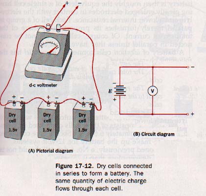
Observe that the positive terminal of one cell is connected to the external circuit, and the negative terminal is connected to the positive terminal of a second cell. The negative terminal of this cell is connected to the positive terminal of a third cell, and so on. The negative terminal of the last cell in the series is connected to the load to complete the circuit.
Thus the cells are joined end to end and the same quantify of electricity must flow through each cell. Suppose the battery is thought of as a group of electron pumps connected in series (adding). Each electron pump (cell) removes electrons of low potential energy from its anode and supplies electrons of high potential energy to its cathode. The first pump lifts electrons to a certain level of potential energy, the second pump takes them from this level to the next higher level, the third lifts them to a still higher potential energy level, and so on.
Similarly, the emfs of the cells are added to give the emf of the battery. A battery made up of cells connected in series has the following characteristics:
1. The emf of the battery is equal to the sum of the emfs of the individual cells.
2. The current in each cell and in the external circuit has the same magnitude throughout.
3. The internal resistance of the battery is equal to the sum of the internal resistances of the individual cells.
In a parallel combination of cells, all negative terminals are connected together. One side of the external circuit is then connected to any one of these common terminals. The positive terminals are connected together and the other side of the external circuit can be connected to any one of these common terminals to complete the circuit. See Figure 17-13.
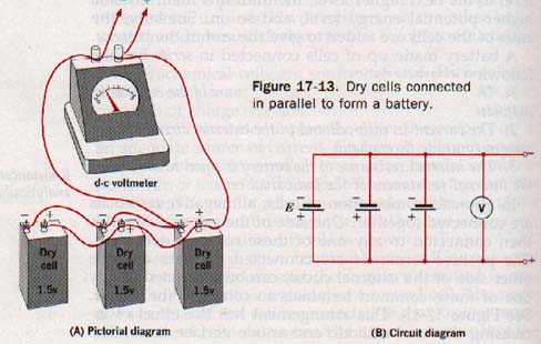
This arrangement has the effect of increasing the total cathode and anode surface areas. The battery is then roughly the equivalent of a single cell having greatly enlarged electrodes in contact with the electrolyte and a lower internal resistance. Each cell of a group in parallel merely furnishes its proportionate share of the total circuit current. Of course, cells should not be connected in parallel unless they have equal emfs.
A battery of identical cells connected in parallel has the following characteristics:
1. The emf is equal to the emf of each separate cell.
2. The total current in the circuit is divided equally among the cells.
3. The reciprocal of the internal resistance of the battery is equal to the sum of the reciprocals of the internal resistances af the cells.
The lead-acid storage battery for automobiles with 6-volt electric systems consists of three cells connected in series. The emf is approximately 6.6 volts. Six cells are connected in series to make up the battery for 12-volt systems.
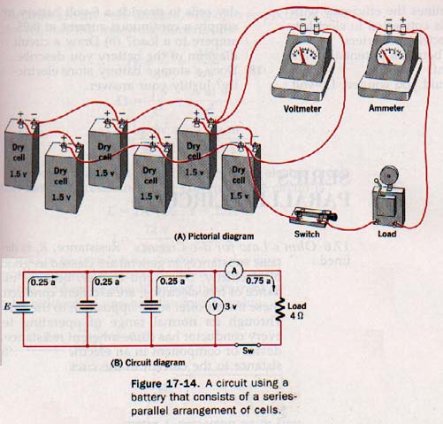
As mentioned previously, a No. 6 dry cell should not be required to deliver more than 0.25 ampere of continuous current. Suppose we have an electric device designed to perform with a 0.75 ampere continuous current in a 3-volt circuit. How should the 1.5 volt dry cells be grouped to make up the battery for operating the device? Certainly, two dry cells in series would provide an emf of 3 volts for the circuit. Three cells in parallel would require no more than 0.25 ampere from each cell. Thus a series-parallel arrangement of dry cells, as shown in Figure 17-14, is appropriate.
SERIES AND PARALLEL CIRCUITS
17.6 Ohm's Law for d-c Circuits Resistance, R, is de fined as the opposition to the flow of electric charge. Metallic substances in general are classed as good conductors of electricity.
Silver and copper, because of their abundance of free electrons, are excellent conductors; yet even these metals offer some opposition to the current in them. Through its normal range of operating temperatures, every conductor has some inherent resistance. Thus every device or component in an electric circuit offers some resistance to the current in the circuit.
Copper wire is used to connect various circuit components in electric circuits because ordinarily its resistance is low enough to be neglected. Certain metallic alloys offer unusually high resistance to the flow of electricity; nichrome and chromel are notable examples. Spools wound with wire made from these alloys can be used in an electric circuit to provide either fixed amounts of resistance or variable resistance in definite amounts.
Carbon granules can be mixed with varying amounts of clay and molded into cylinders having a definite resistance. These devices, known as carbon resistors, are commonly used in electronic circuits.
The German physicist Georg Simon Ohm (1789-1854) discovered that in a closed circuit the ratio of the emf of the source to the current in the circuit is a constant. This constant is the resistance of the circuit. The above statement, known as Ohm's law of resistance, describes a basic relationship in the study of current electricity. It can be stated mathematically:
E/I = R or E = IR
Where E is the electromotive force in volts, I is the current in amperes, and R is the resistance in ohms, Ω.
17.8 Resistances in Series If several electric devices are connected end to end in a circuit, electricity must flow through each in succession. There is a single path for the moving charge. The same current must be in each device or else there would be an accumulation of charge at different points around the conducting circuit. We know that a charge can be accumulated on a conductor only if it is isolated. An electric circuit with components arranged to provide a single conducting path for current is known as a series circuit.
Series-circuit operation has several inherent characteristics. If one component of a series circuit fails to provide a conducting path, the circuit is opened. Each component of the circuit offers resistance to the current, and this resistance limits the current in the circuit according to Ohm's law.
When components are connected in series, their resistances are cumulative. The greater the number of resistive components, the higher is the total resistance and the smaller is the current in the circuit for a given applied emf. Obviously, since the current must be the same at all points in the circuit, all devices connected in series must be designed to function at the same current magnitude.
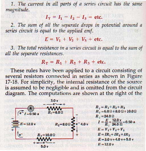
From Ohm's law, the drop in potential across each component of a series circuit is the product of the current in the circuit and the resistance of the component. Electrons lose energy as they fall through a difference of potential; in a series circuit these losses occur in succession and are therefore cumulative. The drops in potential across successive components in a series circuit are additive, and their sum is equal to the potential difference across the whole circuit.
These observations are summarized by stating three cardinal rules for resistances in series.
Kirchhoff's Laws of Series Circuits:
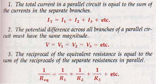
17.9 Resistances in Parallel Some of the characteristics of series operation of electric devices were mentioned in the preceding section. It would be quite disconcerting to have all the lights go out in your home each time one lamp were turned off.
For this reason each lamp is on a separate circuit so that each is operated independently. Such lamps are connected in parallel. A parallel circuit is one in which two or more components are connected across two common points in the circuit to provide separate conducting paths for current.
Since there can be only one difference of potential between any two points in an electric circuit, electric devices are appliances connected in parallel should usually be designed to operate at the same voltage. The currents in the separate branches must vary inversely with their separate resistances since the same potential difference exists across each branch of the parallel circuit.
Kirchhoff's Laws of Parallel Circuits:
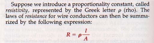
27.1 The Laws of Resistance Various factors affect the resistance of a conductor:
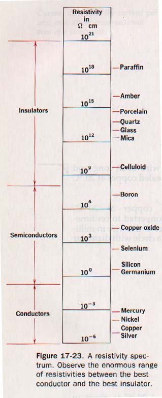
1. Temperature. The resistance of all substances changes to some degree with changes in temperature. In fhe case of pure metals and most metallic alloys, the resistance increases with a rise in temperature. On the other hand, carbon, semiconductors, and many electrolytic solutions, show a decrease in resistance as their temperature is raised.
2. Length. Resistances in series are added to give the total resistance of the series circuit. From this fact we can conclude that 10 meters of a certain conductor should have a resistance 10 times that of 1 meter of the same conductor. Experiments prove this relationship to be true: The resistance of a uniform conductor is directly proportional to the length of the conductor.
3. Cross-sectional area. If three equal resistances are connected in parallel in an electric circuit, the equivalent resistance is one-third the resistance of any one branch. The resistance varies inversely as the cross-sectional area.
4. Nature of the materials. A copper wire having the same length and cross-sectional area as an iron wire offers about one-sixth the resistance to an electric current. A similar silver wire presents even less resistance. The resistance of a given conductor depends on the material of which it is made. Taking these four factors into account, several useful conclusions become apparent. For a uniform conductor of a given material and temperature, the resistance is directly proportional to the length and inversely proportional to the cross-sectional area.
Measuring Resistance:
There are several methods of measuring the resistance of a circuit component. Two methods utilizing apparatus normally available in the laboratory will be discussed here. These are the voltmeter-ammeter method and the Wheatstone bridge method.
1. The voltmeter-ammeter method. Ohm's law applies equally well to any part of an electric circuit that does not contain a source of emf and to an entire circuit to which an emf is applied. For a part of a circuit
V = IR so R = V/I
If the potential difference, V, across a resistance component is measured with a voltmeter and the current, I, in the resistance is measured with an ammeter, the resistance, R, can be computed.
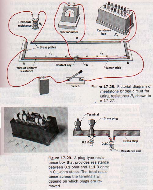
2. The Wheatstone bridge method. A precise means of determining resistance utilizes a simple bridge circuit known as the Wheatstone bridge. It consists of a source of emf, a galvanometer, and a network of four resistors. If three are of known resistance, the resistance of the fourth can be calculated.
The circuit diagram of a Wheatstone bridge is shown in Figure 17-27, in which an unknown resistance, Rx may be balanced against known resistances R1, R2 and R3. A galvanometer is bridged across the parallel branches ADB and ACB. By adjusting R1, R2 and R3 the bridge circuit can be balanced and the galvanometer will show zero current. When the bridge is balanced in this manner, there can be no potential difference between C and D, since the galvanometer indicates zero current. We solve for the unknown resistance by proportions.
The Wheatstone Bridge
SUMMARY
Electric current is the rate of flow of charge in a circuit. The charge carriers in metallic conductors are electrons. The current in these conductors is an electron current and its directional sense is from negative to positive. A continuous current requires a source of emf.
There are several sources of emf and continuous current, each of which transforms energy of some form to electric energy.
The dry cell is a common source of emf that supplies direct current to a circuit. It is a primary cell that is a form of voltaic cell in which chemical energy is converted to electric energy.
Electric cells can be combined in series, in parallel, or in series-parallel to form batteries of suitable characteristics for a given circuit. All circuit components offer some resistance to the current in a closed circuit.
The relationship between resistance, current, and potential difference is expressed by Ohm's law. Ohm's law applies to an entire circuit or to any part of a circuit.
Resistances can be connected in series, in parallel, or in series-parallel combinations called networks. Networks can be reduced to simple equivalent circuits in which those components in parallel are reduced to their series equivalents. Equivalent circuit problems are solved by the application of Ohm's law for series circuits.
The resistance of a metal conductor depends on the temperature, length, cross-sectional area, and identity of the metal. From a knowledge of these factors, the laws of resistance are formulated and a property of materials called resistivity is defined. Resistivity depends on only the identity of the material and its temperature.
The resistance of a circuit element can be measured directly by the voltmeter-ammeter method or by the Wheatstone bridge method. The voltmeter-ammeter method is rapid, and the Wheatstone bridge method is more precise.
VOCABULARY
anode, battery, cathode, closed circuit, cryogenics, drift velocity, electric current, electrode, electrolyte, emf, equivalent resistance, external resistance, galvanometer, internal resistance, load resistor, open circuit, parallel circuit, Peltier effect, photoelectric effect, piezoelectric effect, primary cell, resistance, resistance network, resistivity, Seebeck effect, semiconductor, series circuit, thermocouple, Wheatstone bridge.
 Assignment Sheet for this Research Text Only.
 Go to Textbook Assignments for Portfolio:
.................................First Semester
.................................Second Semester