Diffraction and Polarization
Diffraction and Polarization
The purpose of this is to give quick reference to information or to use in an emergency (like if your text has accidentally been left under your desk at school).
This is NOT intended to replace reading the text with its excellent photographs, diagrams, charts, and tables.
DIFFRACTION AND POLARIZATION
The equation for the diffraction of light was derived by W Henry Bragg and his son, William Lawrence Bragg, by crystal structures with X rays. In 1915, the Braggs jointly the Nobel Prize in Physics for this work, which provided a valuable tool for the study of atomic structure.
INTERFERENCE AND DIFFRACTION
15.1 Double Slit Interference The superposition of identical wave trains traveling in the same or opposite direction illustrates the phenomenon of interference of waves of the same amplitude and wavelength projected in the same direction by two loudspeakers provide an interference pattern in which alternate regions of reinforcement and cancellation can be found.
Two identical waves traveling in opposite directions on a stretched string interfere and produce a standing wave pattern.
The interference of two water waves of identical wavelength is easily observed in the laboratory using the ripple tank. More precise studies of such wave behavior are made by photographing light reflections from the surface of a mercury ripple tank.
Interference and superposition topics can be reviewed by referring to Sections 10.14 through 10.16.
The superposition principle holds for these wave disturbances in material media and for light waves and other electromagnetic waves in free space. Thus light shows interference: the mutual effect of two beams of light that results in a loss of intensity in certain regions (destructive interference) and a reinforcement of intensity in other regions (constructive interference) .
The English physician and physicist Thomas Young (1773-1829) first demonstrated interference of light in 1801 and showed how this phenomenon supports the wave theory of Huygens.
Two narrow slits, as shown in Figure 15-1, about 1 mm apart in a piece of black paper are used to observe a narrow source of light, S, placed 2 or 3 meters away.
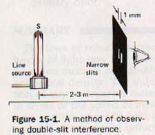
A series of narrow bands alternately dark and light is seen in the center of a fairly wide band of light. See Figure 15-2.
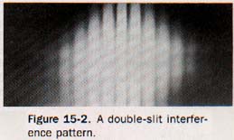
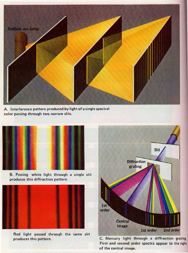
If a red filter is placed between the source and the slits so that a single spectral color is the light source, a series of red and black bands is seen. A double-slit interference pattern seen from a monochromatic light is shown in
Plate VIII(A).
A wavefront diagram of double-slit interference with a monochromatic light source is shown in Figure 15-3.
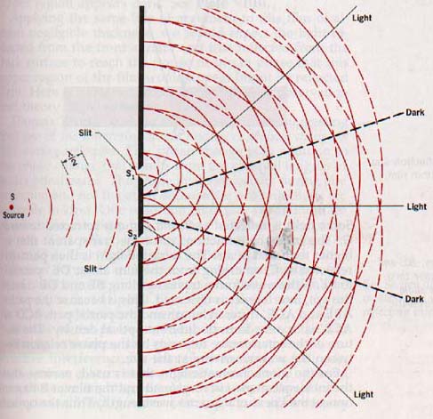
Slits Si and S2 are equidistant from the source S. As light from 15-3 with the photograph producing new wave fronts in phase with each other. These waves travel out from S1 and S2 producing bright bands of light due to reinforcement where constructive interference occurs and dark bands due to cancellation Figure 15-3. A wavefront diagram where destructive interference occurs.
15.2 Interference in Thin Films Sir Isaac Newton knew about the color fringes produced by thin films. He devised experiments to determine the film thickness that corresponds to a specific color.
Interference of light was unknown in his time, however. his corpuscular explanation of the partial reflection and partial refraction of light at the interface of two different transmitting media is inadequate in view of modern theories of light.
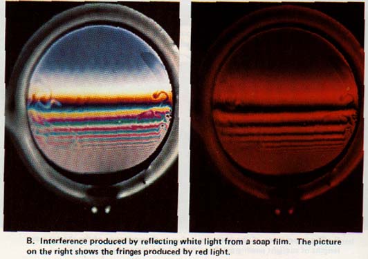
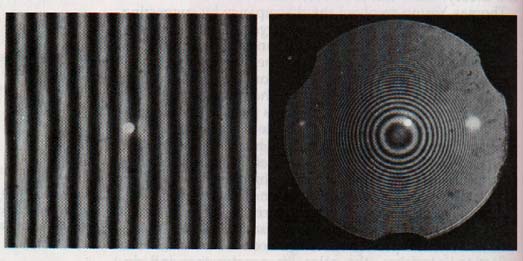
When viewed by reflected white light, thin transparent soap films, oil slicks, and wedge-shaped films of air show varying patterns of colors. When illuminated by monochromatic light, alternate bright and dark regions are observed, and the positions of the bands shift as the color of the monochromatic light is changed.
Thomas Young explained this thin-film phenomenon in terms of the interference of light waves.
A ray of monochromatic light is incident on a thin transparent film at a small angle i, as shown in Figure 15-4.
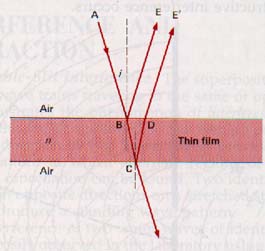
The two reflected waves, BE and DE', are coherent because they both originate from the same point A on the monochromatic source.
Some light is reflected at B and some is refracted toward C. The index of refraction, n, of the transparent film is higher than that of air.
The refracted light is then partially reflected at C, emerging from the film along DE' parallel to BE. If the wave fronts traveling along BE and DE' reach the eye, interference is observed.
This is because the paths ABE and ACE' differ in length and the partial path BCD of ACE' is in a medium of different optical density. The nature of the interference depends on the phase relation between the waves arriving at the eye.
For the monochromatic light that is used, assume that the incidence angle i is very small and the film at B has an optical thickness of a quarter wavelength. Thus the optical path in the thin film from B to C is one-quarter wavelength. from C to D is another one-quarter wavelength.
Light emerging from the film at D is therefore one-half wavelength behind that reflected at B and will be expected to interfere destructively causing the film to appear dark.
Now if we assume the film has an optical thickness of a half wavelength, light reflected from the lower surface of the film will emerge at D a whole wavelength behind that reflected from the upper surface at B.
The waves will be expected to interfere constructively causing the film to appear bright at this point. Observation of reflection light from thin films shows that a reverse effect actually occurs.
Thus, the quarter-wave point appears bright and the half-wave point appears dark.
This anomalous situation prevails whenever air is on both sides of the film. It is easily observed in soap films. If a soap film is supported vertically, as it drains its upper region it will become quite thin and a very small fraction of a wavelength in thickness just before it breaks.
If observed by reflected monochromatic light at this moment, this upper region appears dark.
Plate VI(B).
Applying the same line of argument to this film of almost negligible thickness, we would expect the light reflected from the front surface and that reflected from the back surface to reach the eye so nearly in phase that this upper region of the film would appear bright by reflected light. Here is a clear-cut discrepancy between observation and theory. How can it be reconciled?
Thomas Young resolved the discrepancy by suggesting one of the interfering waves undergoes a phase change of during reflection. This phase change is in addition to phase change that results from the unequal lengths of their optical paths.
The phase inversion occurs during one and not the other because the two reflections are in kind. One reflection takes place at an interface which the medium beyond has the higher index of refraction corresponds to that at point B in 15-4.
The reflected wave is inverted in phase. The other occurs at an interface at which the medium beyond the lower index of refraction. This reflection corresponds that at point C in Figure 15-4.
Here, the reflected wave experiences no change in phase because of the phase-inverting effect of one of the two interacting interfaces, the rules for constructive and destructive interference for thin films bounded on both sides a medium of lower index of refraction are just the opposite those we might expect. Maximum constructive interference occurs with such thin films if the optical path difference is an odd number of half wavelengths.
This happens where the thickness is an odd number of quarter wavelengths. Maximum destructive interference occurs if the optical path is a whole number of wavelengths. Here the film an even number of quarter wavelengths.
The vertically supported soap films of Plate VI(B) usually increase in thickness toward the bottom as drain.
A vertical cross section of such a film would have a wedge-like appearance. As the thickness increases, odd wavelength requirements for the reinforcement of different orders and the even wavelength requirement for their cancellation met at successive intervals down the film.
The soap shown on the left of Plate VI(B) therefore reflects white light as a succession of colors at intervals down the film. An air film between two optically flat glass plates duces a regular pattern of interference fringes. Irregular surfaces produce irregular patterns of interference
Using interference patterns, inspection techniques been developed that make extremely high precision insturements possible. Test plates can be polished flat with a tolerance of approximately 5 x 10⁻⁷ cm. Interference techniques are used to establish standards of measurement in many mechanical processes.
The interferometer is an instrument that uses interference in the measurement of distance in terms of known wavelengths of light or in the measurement of wavelengths in terms of a standard of length.
15.3 Diffraction of Light According to the wave theory, light waves should bend around corners although our common experience with light shows that it travels in straight lines.
Under some conditions light waves do bend out of their straight paths. When light waves encounter an obstruction with dimensions comparable with their wavelengths, the light spreads out and produces spectral colors due to interference.
Figure 15-5
The spreading of light into a region behind an obstruction is called diffraction. A slit opening, a fine wire, a sharp-edged object, or a pinhole can serve as a suitable obstruction in the path of a beam of light from a point source.
It is possible to see diffraction fringes if one peers between two fingers at a distant light source. With the fingers held close to the eye and brought together to form a slit opening, dark fringes will be seen just before the light is shut out.
Diffraction effects, such as indistinct edges of shadows and shadow fringes, are known to have been observed as early as the seventeenth century. However, before the discovery of interference in 1801, neither the wave theory nor the corpuscular theory could offer a suitable explanation for these diffraction effects.
In 1816 the French physicist A. J. Fresnel (fray-nel) (1788-1827) demonstrated that the various diffraction phenomena are fully explained by the interference of light waves.
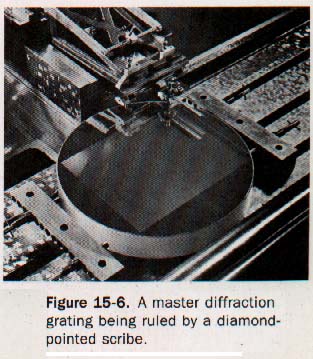
Very useful diffraction patterns can be produced by illuminating an optical surface, either plane or spherical concave, that has many thousands of straight, equally spaced grooves as diffraction gratings. Light is diffracted when it is transmitted through or reflected from the narrow spaces between the ruled lines.
Standard gratings can have as many as 12,000 ruled lines per centimeter of grating surface. X rays are investigated with ordinary diffraction gratings set with their surface at a low angle to the rays.
The gratings thus have the equivalent of many lines per centimeter. Gratings are generally superior to optical prisms for displaying the length a spread of spectra. However, grating spectra tend to be less intense than those formed by prisms.
25.4 Wavelength by Diffraction A transmission grating placed in the path of plane waves disturbs the wave front because the ruled lines are opaque to light and the narrow spacings between the lines are transparent. These spaces provide a large number of fine, closely spaced transmission slits.
Figure 15-6
New wavelets generated at these slits interfere in such a way that several new wave fronts are established. One wave front travels in the original direction and the other wave fronts travel at various angles from this direction depending on their wavelength. Suppose a single narrow slit is illuminated by white light and viewed through a transmission grating. A image of the illuminated slit is seen directly in line the slit opening. In addition, pairs of continuous spectra are observed, each pair equally spaced on opposite of the principal image.
If we illuminate the slit with monochromatic light, successive pairs of slit images of decreasing intensity will pear on opposite sides of the principal image. The images forming the first pair are known as first images, those forming the second pair as second images, etc.
In Figure 15-7, A and B are parallel spaces between ruled lines on a diffraction grating. They act as adjacent transmission slits, being uniformly separated by the distance d, called the grating constant.
Monochromatic light from a distant illuminated slit traveling normal to the grating surface produces secondary wavelets simultaneously at A and B. A new wave front of these wavelets along MN and produces the principal image of the slit at N.
Fig 15-7
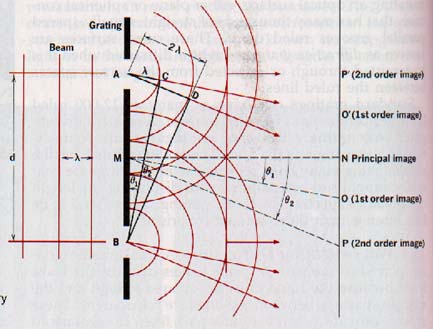
A given wavelet from B and the first preceding wavelet from A produce a wave front CB that travels along MO and gives a first-order image of the slit at O. Similarly, a given wavelet from B and the second preceding wavelet from A give a wave front DB that yields a second-order image at P, etc.
15.5 Single-Slit Diffraction According to Huygens' principle, every point on an advancing wave front can be regarded as a new source of disturbance from which secondary waves spread out as spherical wavelets. If a barrier with a narrow slit opening is placed in the path of advancing plane waves, the disturbance will be transmitted by the slit to the region beyond the barrier.
Figure 15-8
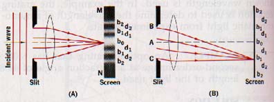
When the width of the slit opening is reduced to only a few wavelengths of the light, a broad region MN is illuminated by the slit. Experiments show that the central portion of this region is always brighter than the remote portions that reveal diffraction fringes of diminishing intensity. Examples of single-slit diffraction patterns are shown in Plate VIII(B) (above).
In Figure 15-8(B) the point b, lies on the perpendicular bisector of the slit and is equidistant from points B and C. Because the distance from the slit to the screen is very large compared with the width of the slit, point bo is essentially equidistant from all points along the line BAC. Thus the wavelets originating simultaneously from all points along BA and from all points along AC will reach bo in phase and the screen in this region will be bright.
At points dl, above and below bo, where the distance from B and C is different by a whole wavelength, the distance from A and C is different by a half wavelength. For every point along CA there is a corresponding point along BA that is a half wavelength different in distance from dl.
Therefore wavelets arriving at d1 from one half of the slit will be annulled by the wavelets arriving from the other half of the slit. The region of dl will be dark. Beyond points dl there are points bl where the distance from B and C is different by 1.5 wavelengths.
Now we can think of the slit opening as being divided into three equal parts. Wavelets from one part arrive at bl a half wavelength behind wavelets from the second part. Wavelets from these parts of the slit opening interfere destructively, while wavelets arriving from the third part produce brightness at b,.
However, the illumination at b, will be lower than that at bo since only one-third of the slit opening contributes to the brightness of these regions. By the same reasoning the regions of d2 where the difference in distance from B and C is 2 wavelengths, will be dark.
Similarly, the regions of b2 will be bright. Thus a series of alternate bright and dark regions appears on either side of bo. The intensity of these regions decreases as the distance from bo increases.
POLARIZATION
15.6 Polarization of Transverse Waves The general wave properties of rectilinear propagation in a homogeneous medium--reflection, refraction, interference, and diffraction are clearly recognized in the behavior of light as well as in sound and water disturbances.
In Chapter 12 we considered a particle model of light that at one time was as successful as the wave model in explaining rectilinear propagation, reflection, and refraction.
Only interference and diffraction failed to accommodate the particle model. They required a wave model for explanation. Thus interference and diffraction give the best evidence that light has wavelike characteristics.
Before the introduction of the electromagnetic theory, light was assumed to be a longitudinal wave disturbance. Electromagnetic theory predicts that light is a transverse wave.
Sound waves are longitudinal disturbances and water waves have both transverse and longitudinal characteristics. From interference or diffraction experiments, we can infer nothing concerning the transverse nature of light waves since both sound and water waves show these properties. What experimental basis do we have that supports the theoretical prediction that light waves are transverse?
Fresnel observed that a beam of light falling on a calcite crystal was separated into two beams that were incapable of producing interference fringes. Young suggested that this could be explained by assuming that the light consisted of transverse waves that were separated into component waves having oscillating planes at right angles to each other.
He called this a plane-polarization effect. Many experiments with calcite and other similar materials have demonstrated the correctness of Young's polarization hypothesis.
Plane-polarized light is light in which the distance oscillations are confined to a single plane that includes the line of image propagation. Transverse waves but not longitudinal waves can be polarized.
This is because the oscillations of transverse waves are independent and randomly oriented. Longitudinal waves vibrate along only one line of direction, and that direction is parallel to its propagation.
Light radiated by ordinary sources is unpolarized since the primary radiators, the atoms and molecules of the light source, oscillate independently. Beams of unpolarized light are made up of independent wave trains with oscillation planes oriented in a random manner about the line of propagation.
Diagrammatically, we can represent unpolarized light being propagated in space by a system of light vectors as shown in Figure 15-9(A).
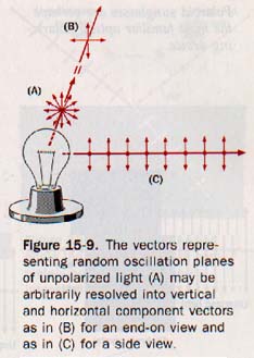
It is customary to resolve these vectors into vertical and horizontal components as at (B), which is a convenient but entirely arbitrary orientation. Figure 15-9(C) represents a side view of (B) in which the horizontal component vectors are perpendicular to the page. It is customary for the light vectors of Figure 15-9 to represent the oscillating electric components of the electromagnetic (light) waves.
Ordinary light can become plane-polarized through interactions with matter. The scattering effect of small particles (see Section 15.11) is accompanied by a polarization effect.
Polarization can also result from reflection of light from various surfaces, from refraction of light through some crystals, and from selective absorption of light in some crystals.
A simple mechanical model can be used to illustrate the polarization concept. Suppose we set up transverse waves in a rope passed through a slot as shown in Figure 15-10.
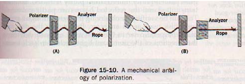
We can readily see that vibrations are transmitted beyond the slot only when the vibrating plane of the rope and the plane of the slot are aligned. We shall call this frame of slots the polarizer. A second slot, parallel to the first, will transmit the waves. See Figure 15-10(A). If the second slot is perpendicular to the first slot, it obstructs them. See Figure 15-10(B).
We shall call this second frame of slots the analyzer.
If the rope is replaced by a long coiled spring, longitudinal waves set up in the spring will pass through the slots regardless of their orientation. Polarization is a property of transverse waves.
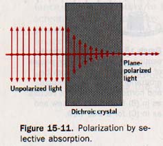
15.7 Selective Absorption It is known that crystalline substances transmit light in one plane of polarization and absorb light in other polarization planes. Tourmaline is such a material.
Unpolarized light incident on a tourmaline crystal emerges as green, plane-polarized of low intensity. This property of crystals in which .one polarized component of incident light is absorbed and other is transmitted is called dichroism. See Figure 15-11.
Dichroic crystals of quinine iodosulfate transmit polarized light very efficiently but the crystals are small for practical use. In 1935 Edwin H. Land developed a method of imbedding these crystals in cellulose film so that the dichroic properties of the crystals were retained. This highly efficient polarizing film is known commercially as Polaroid.
Improved Polaroid sheets have been developed in which polarizing molecules, rather than crystals, are imbedded in appropriate films.
Figure 15-12
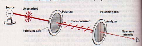
Polaroid disks in use. One acts as a polarizer and the other
as an analyzer. notice that the polarizing axis of each
disk is marked on the rim.
15.8 Polarization by Reflection Sunlight from the surface of calm water or from a level highway be quite objectionable to the observer. Sunglasses polarizing films reduce the intensity of these by rotating the lenses slightly from side to side the refections are seen to pass through a minimum, indicating these rays are partially polarized.
Ordinary light incident obliquely on the surface glass plate is partly reflected and partly refracted. Both transmitted and the reflected beams are partly polarized. This can be verified by observing the light through a polarizing disk used as an analyzer.
By rotating the disk in a plane perpendicular to the light axis, one can determine the direction of the dominant light vectors in each beam.
The component of the incident light lying in the plane parallel to the surface of the glass is largely reflected. The component lying in the plane perpendicular to the surface is largely refracted.
A particular angle of incidence at which polarization of the reflected light is complete, known as the polarization angle, can be found experimentally.
Polarization by reflection is shown in Figure 15-13.
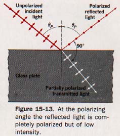
At the polarizing angle the reflected beam is of low intensity and the reflectance is about 15%. The refracted beam, which is not completely polarized, is bright. The intensity of the plane-polarized reflected beam can be increased by combining reflections as a result of stacking several plates. The combined refracted beam becomes less intense but more completely plane-polarized.
15.9 Polarization by Refraction If a thick glass plate is placed on a printed page, the print viewed through the glass may appear displaced because of refraction. A natural crystal of calcite placed on the page shows two refracted images of the print, as shown in Figure 15-14.
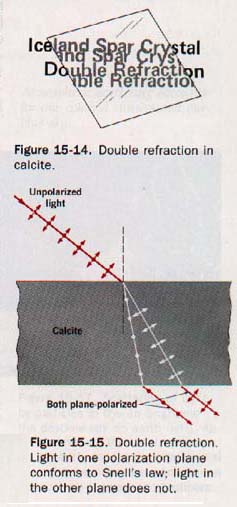
Calcite and many other crystalline materials exhibit this property of double refraction.
Upon entering a doubly refracting crystal such as calcite, a beam of unpolarized light can divide into two beams at the crystal surface. This separation is shown diagtammatically in Figure 15-15 (above).
Analysis of these separate beams with polarizing disks reveals that they are plane polarized with their planes of polarization perpendicular to each other.
Experimentally, one of the polarized beams can be shown to follow Snell's law; the other beam does not. Using monochromatic sodium light of 5893 A and measuring the angles of incidence and refraction, we find that one beam yields a constant index of refraction of 1.66.
However, the other beam shows an index of refraction that varies from 1.49 to 1.66 depending on the angle of incidence. This difference suggests that the light energy is propagated through the crystal at different speeds that are determined by the orientation of the light planes with the crystal lattice.
Calcite crystals are sometimes polished, cut through, and cemented back together in such a way that one of the polarized beams is totally reflected at the cemented face. Such a crystal, known as a Nicol prism, can be used to produce a beam of completely polarized light.
15.10 Interference Patterns The two plane-polarized beams of light that emerge from a doubly refracting crystal cannot be made to interfere with each other even though they are transmitted through the crystal at different speeds. This is because their planes of polarization are perpendicular to each other.
It follows that if two light waves interfere, their oscillations (or components of these oscillations) must lie in the same plane.
If polarized light is incident on a doubly refracting crystal at the proper angle, the emerging beams are found to interfere as they pass through an analyzer disk. The analyzer passes only the components of these perpendicularly polarized rays that lie in its transmission plane.
Those waves from the two beams having a phase difference of an odd number of half wavelengths interfere destructively, the corresponding color is removed, and its complement is observed.
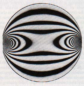
Materials, such as glass and Lucite, that become doubly refracting when subjected to mechanical stress are said to be photoelastic. When a photoelastic material is placed between polarizing and analyzing disks, the strain patterns (and thus the stress distributions) are revealed by interference fringes, as shown in
Figure 15-16
15.11 Scattering A beam of light traveling in dust-free air cannot be seen even in a darkened room. If, however, there is dust in the path of the beam, it becomes visible by reflection of light from the surface of the particles.
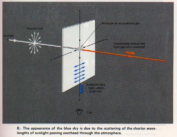
Suppose a beam of white light travels in a medium containing suspended particles that have diameters smaller than the mean wavelength of visible light. When observed at right angles to its path, the beam has a bluish cast
When observed in its path, the remaining transmitted beam has a red-orange cast. With certain concentrations of suspended particles, the bluish light sent off radially becomes quite intense and the transmitted light acquires a more intense red-orange color.
An excess of shorter wavelengths is emitted at right angles to the path of the beam and an excess of longer wavelengths is transmitted along the path of the beam.
This phenomenon, known as scattering, occurs when a beam of light encounters suspended particles with dimensions that are small compared to the wavelengths of the light.
If we look at blue sky light through a polarizing disk, we observe that it is plane polarized. By selecting a point in the blue sky near the horizon with the sun overhead, we find the scattered light to be horizontally polarized.
In the late afternoon near the time of sunset, sunlight must travel a maximum distance through the atmosphere to reach an observer. The setting sun has a yellow to red hue.
The sunlight reflected to an observer from clouds near the sight line of the observer has the yellow or red hue characteristic of the sunset. Much of the energy in the blue region of the sunlight has been removed by the scattering effect of the atmospheric gas molecules.
Under these conditions the transmitted light is largely yellow-red. This accounts for the blue appearance of the sky and the reddish appearance of the setting sun. See Plate V(B).
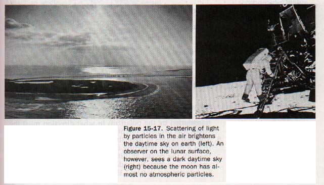
If the earth had no envelope of atmospheric gases, the sky would appear black to an observer on the surface of the earth since there would be no scattering of sunlight passing overhead. Astronauts have observed the blackness of outer space while in flight beyond the earth's atmosphere.
Plate V(B)
Scattering is responsible for certain other natural color phenomena known as structural colors (in contrast to the pigment colors that we have already considered). The colors of many minerals are structural. The blue color of a bluejay's feathers results from scattering of light by tiny bubbles of air dispersed through the feather structure. The blue color in the eyes of a person is also a structural color; there is no blue pigment in the irises of blue eyes.
15.12 OpticaI Rotation A number of substances, such as quartz, sugar, tartaric acid, and turpentine, are said to be optically active because they rotate the plane of polarized light.
A water solution of cane sugar (sucrose) rotates the plane of polarization to the right. For a given path length through the solution, the angle of rotation is proportional to the concentration of the solution.
In analytical procedures chemists find numerous applications of this property of optically active substances. Instruments for measuring the angle of rotation under standard conditions are known as polarimeters; those used specifically for sugar solutions are called saccharimeters.
SUMMARY
Interference of light can be compared with interference in other wave disturbances. It is interpreted in terms of the superposition principle.
Thomas Young first demonstrated interference of light and related double-slit interference and thin-film interference to Huygens' wave theory.
The analysis of thin-film interference requires an understanding of the nature of wave reflections at interfaces where the medium beyond has the higher or the lower index of r
The various diffraction phenomena are explained by the interference of light waves.
Diffraction gratings produce diffraction patters by the reflection or transmission of incident light.
The wavelength of light can be determined experimentally from measurements of grating spectra.
Polarization of light depends on the transverse nature of light waves. Polarization is a property of transverse waves. Light may be plane polarized by the selective absorption of certain crystals, by reflection from certain smooth surfaces, and by doubly refracting crystals.
Photoelastic substances become doubly refracting when subjected to mechanical stress. The scattering of sunlight accounts for the blue appearance of sky light and the reddish appearance of sunset and sunrise.
Substances that rotate the plane of polarized light are said to be optically active.
VOCABULARY
constructive interference, first-order image, plane-polarized light, destructive interference, grating constant, polarimeter, dichroism, interference, saccharimeter, diffraction, interferometer, scattering, diffraction angle, Nicol prism, second-order image, diffraction grating, optically active substance, structural color.
Ah Yaz Indeed!
 Assignment Sheet for this Research Text Only.
 Go to Textbook Assignments for Portfolio:
.................................First Semester
.................................Second Semester