Refraction of Light
Refraction of Light
The purpose of this is to give quick reference to information or to use in an emergency (like if your text has accidentally been left under your desk at school).
This is NOT intended to replace reading the text with its excellent photographs, diagrams, charts, and tables.
REFRACTION
l4.1 The Nature of Optical Refraction In Section 10.12 we discussed refraction as a property of waves. Now we shall examine the refractive behavior of light and relate this behavior to its wavelike nature.
When aiming a rifle at a target, one relies on the common observation that light travels in straight lines. It does so, however, only if the transmitting medium is of the same optical density throughout. Optical density is a property of a transparent material that is an inverse measure of the speed of light through the material.
Consider a beam of light transmitted through air and directed onto the surface of a body of water. Some of the light is reflected at the interface (boundary) between the air and water; the remainder enters the water and is transmitted through it.
Because water has a higher optical density than air, the speed of light is reduced as the light enters the water. This change in the speed of light at the air-water interface is diagrammed in Figure 14-2.
A ray of light that strikes the surface of the water at an oblique angle (less than 90" to the surface) changes direction abruptly as it enters the water because of the change in speed. The reason for this change in direction with a change in speed can be illustrated if we redraw the wavefront diagram of Figure 14-2(A) to make the angle of the incident ray oblique, as in Figure 14-2(B).
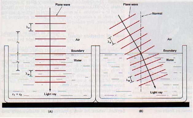
When interpreting this diagram, you should remember that a light ray indicates the direction the light travels and is perpendicular to the wave front.
We have already defined refraction as a bending of a wave disturbance. (See Section 10.12.) This bending of a light ray is called optical refraction. Optical refraction is the bending of light rays as they pass obliquely from one medium into another af different optical density.
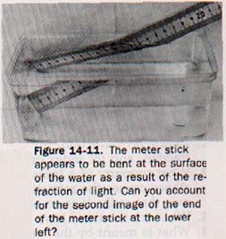
Because of refraction, a fish observed from the bank appears nearer to the surface of the water than it actually is. A teaspoon in a tumbler of water appears to be bent at the surface of the water. A coin in the bottom of an empty teacup that is out of the line of vision of an observer may become visible when the cup is filled with water.
14.2 Refraction and the Speed of Light Line MN of Figure 14-3 represents the surface line AO represents a ray of light through the air striking the water at O.
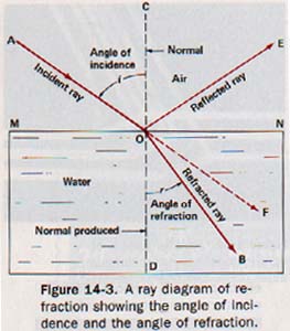
Some of the light is reflected along OE. Instead of continuing in a straight line along OF, the light ray entering the water is bent as it passes from air into water, taking the path OB.
The incident ray AO makes the angle AOC with the normal. Angle AOC is the angle of incidence, i. Recall that the angle of incidence is defined as the angle between the incident ray and the normal at the point of incidence. The refracted ray OB makes the angle DOB with the normal produced. The angle between the refracted ray and the normal at the point of refraction is called the angle of refraction, r. In the examples given so far, the light rays have from one medium into another of higher optical density, with a resulting reduction in speed.
When a ray enters the denser medium normal to the interface, no refraction occurs. When a ray enters the denser medium at an oblique angle, refraction does occur and the ray is bent toward the normal.
What is the nature of the refraction if the light passes obliquely from one medium into another of lower optical density?
Suppose the light source were at B in Figure 14-3. Light ray BO then meets the surface at point 0, and angle BOD is the angle of incidence. Of course some light is reflected at this interface. However, on entering the air the refracted portion of the light takes the path OA.
The angle of refraction in this case is angle COA. It shows that the light is bent away from the normal. When a light ray enters a medium of lower optical density at an oblique angle, the ray is bent away from the normal. Had the light ray entered this less dense medium normal to the interface, no refraction would have occurred.
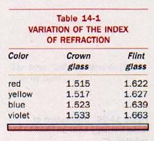
14.3 The Index of Refraction The speed of light in a vacuum is approximately 300,000 kilometers per second. The speed of light in water is approximately 225,000 kilometers per second, or just about three fourths of that in a vacuum. The speed of light in ordinary glass is approximately 200,000 kilometers per second or about two thirds of that in a vacuum.
The ratio of the speed of light in a vacuum to its speed in a substance is called the index of refraction for that substance. For example:
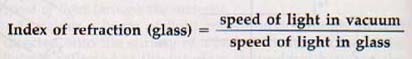
Using the approximate values just given, the index of refraction for glass would be about 1.5 and for water about 1.3.
The index of refraction for a few common substances is given in Appendix B, Table 18. The speed of light in air is only slightly different from the speed of light in a vacuum. Therefore, with negligible error, we can use the speed of light in a vacuum for cases where light travels from air into another medium.
The fundamental principle of refraction was discovered by the Dutch mathematician and astronomer Willebrord Snell (1580-1626). He did not publish his discovery, but his work was taught at the University of Leyden, where he was a professor of mathematics and physics.
The French mathematician and philosopher Rene Descartes (1596-1650) published Snell's work in 1637. Snell's discoveries about refraction were not stated in terms of the speed of light. The speed of light in empty space was not determined until 1676, and the speed in water was not measured until 1850. From his observations, however, Snell defined the index of refraction as the ratio of the sine of the angle of incidence to the sine of the angle of refraction. This relationship is known as Snell's law. If n represents the index of refraction, i is the angle incidence, and r the angle of refraction,
![]()
The sines of angles from 0o to 90o are given in Appendix B, Table 6.
The relationship between Snell's law and the ratio of the speeds of light in air and a refracting medium can be recognized from Figure 14-5. Rays of light travel through the first medium (air) with a speed v1 and enter the refracting medium in which their speed is v2.
Butterfat and margarine have different indexes of refraction. One of the first tests made in a food-testing laboratory to determine whether butter has been mixed with margarine is the measurement of the index of refraction.
The high index of refraction of a diamond furnishes one of the most conclusive tests for its identification.
Because light travels very slightly faster in outer space than it does through air, light from the sun or the stars is refracted when it enters the earth's atmosphere obliquely. Since the atmosphere is denser near the earth's surface, a ray of light from the sun or a star striking the atmosphere obliquely follows a path suggested by the curve shown in Figure 14-6. There is no abrupt refraction such as that which occurs at the interface between two media of different optical densities.
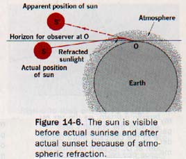
Atmospheric refraction prevents the sun and stars from being seen in their true positions except when they are directly overhead. In Figure 14-6 the Sun appears at S' instead of S, its true position. Since the index of refraction from outer space to air is only 1.00029, the diagram is greatly exaggerated to show the bending.
Refraction of sunlight by the earth's atmosphere causes the sun, when geometrically on the horizon, to appear about one diameter (0.5o) higher than it really is. Around 2 minutes are required for the earth to rotate through 0.5o of arc. Thus, we gain about 4 minutes of additional daylight each day because of atmospheric refraction at sunrise and sunset.
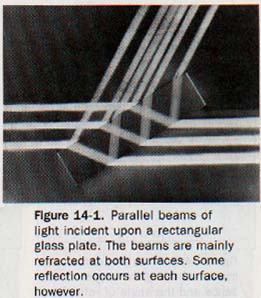
14.4 The Laws of Refraction If the index of refraction of a transparent substance is known, it is possible to trace the path that a ray of light will take in passing through the substance.
In Figure 14-7 rectangle ABCD represents a piece of plate glass with parallel surfaces. The line EO represents a ray of light incident upon the glass at point O. From point O as a center, two arcs are drawn. The radii of these arcs are in the ratio 3/2 based on the index of refraction of the glass being 1.5 and that of the air being 1.
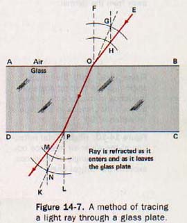
The normal OF is drawn. Then a line is drawn parallel to OF through the point H where the incident ray intersects the smaller arc. This line intersects the larger arc at point G. The line OP, determined by points G and 0, marks the path of the refracted ray through the glass.
If the ray were not refracted as it leaves the glass, it would proceed along the line PK. To indicate the refraction at point P, this point is used as a center and arcs are drawn having the same ratio, 3/2, as before. The normal PL and a line MN parallel to the normal are drawn. The parallel line is drawn this time through point N where the larger arc is intersected by the extension of refracted OP. This line intersects the smaller arc at point M. Points and M determine the path of the refracted ray as it enters the air.
In Figure 14-8 line AD represents a light ray incident upon a triangular glass prism at point D. Passing obliquely from air into glass, the ray is refracted toward the normal along line DB. Observe that at point D angle i in air is larger than angle r in glass.
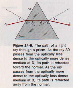
As light ray DB passes obliquely from glass into air at point B, it is refracted away from the normal along line BC. At point B angle i in glass is smaller than angle r in air.
Refraction of light can be summarized in three laws refraction:
1. The incident ray, the refracted ray, and the normal to the surface at the point of incidence are all in the same plane.
2. The index of refraction for any homogeneous medium is a constant that is independent of the angle of incidence.
3. When a ray of light passes obliquely from a medium of lower optical density to one of higher optical density, it is bent toward the normal to the surface. Conversely, a ray of light passing obliquely from an optically denser medium to an optically rarer medium is bent away from the normal to the surface.
18.5 Total Reflection Suppose an incident ray of light, AO, passes from water into air and is refracted along the line OB as shown in Figure 14-9.
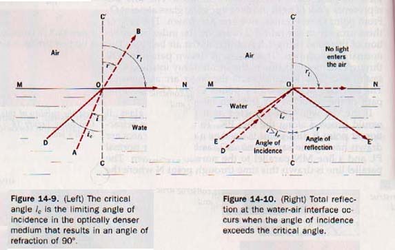
As the angle of incidence, i, is increased, the angle of refraction, r, also increases. When this angle approaches the limiting value, ri = 90o, the refracted ray emerges from the water along a path that gets closer to the water surface. As the angle of incidence continues to increase, the angle of refraction finally equals 90o and the refracted ray takes the path ON along the water surface. The limiting angle of incidence in the optically denser medium that results in an angle of refraction of 90o is known as the critical angle, i,.
The critical angle for water is reached when the incident ray DO makes an angle of 48.5o with the normal; the critical angle for crown glass is 42o, while that for diamond is only 24o.
In Section 14.3 we defined the index of refraction of a material as the ratio of the speed of light in a vacuum (air) to the speed of light in the material or as the ratio sin i / sin r.
In Figure 14-9 the light passes from the optically denser water to the air. Thus in the form of Snell's law, the roles of the angles of incidence and refraction are reversed.
Here the angle of refraction, r, is related to the speed of light in air. The angle of incidence, i is associated with the speed of light in water. The index of refraction of the water in this instance is sin r (air) / sin i (water).
Therefore, in general, where n is the index of refraction of the optically denser medium relative to air and i, is the critical angle of this medium.
If the angle of incidence of a ray of light passing from water into air is increased beyond the critical angle, no part of the incident ray enters the air. The incident ray is totally reflected from the water interface.
In Figure 14-10 EO represents a ray of light whose angle of incidence exceeds the critical angle, the angle of incidence EOC being greater than the critical angle DOC.
The ray of light is reflected back into the water along the line OE', a case of simple reflection in which the angle of incidence EOC equals the angle of reflection E'OC.
Total reflection always occurs when the angle of incidence exceeds the critical angle.
A diamond is a brilliant gem because its index of refraction is exceedingly high and its critical angle is therefore correspondingly small. Very little of the light that enters the upper surface of a cut diamond passes through the diamond, most of the light is reflected internally (total reflection), finally emerging from the top of the diamond.
The faces of the upper surface are cut at such angles as ensure that the maximum light entering the upper is reflected back to these faces.
LENS OPTICS
24.6 Types of Lenses A lens is any transparent object having two nonparallel curved surfaces or one plane surface and one curved surface. The curved surfaces can be spherical, parabolic, or cylindrical. Lenses are usually made of glass but can be made of other transparent materials. There are two general classes of lenses based upon their effects on incident light.
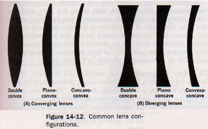
1. Converging lenses. Cross sections of converging lenses are shown in Figure 14-12(A). All are thicker in the middle than at the edge. The concavo-convex lens is known as a meniscus len
Recall that light travels more slowly in glass and other lens materials than it does in air. Light passing through the thick middle region of a converging lens is retarded more than light passing through the thin edge region. Consequently, a wave front of light transmitted through a converging lens is bent as shown in Figure 14-13(A). The plane wave in this diagram is incident on the surface of the converging lens parallel to the lens plane. The wave is refracted and converges at the point F beyond the lens.
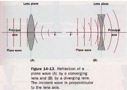
2. Diverging lenses. Lenses that are thicker at the edges than in the middle are diverging lenses. Their cross sections are shown in Figure 14-12(B). The convexo-concave lens is a meniscus lens.
Light passing through the thin middle region of a diverging lens is retarded less than light passing through the thick edge region. A wave front of light transmitted through a diverging lens is bent as shown in Figure 14-13(B).
Observe that the plane wave in this diagram is also incident on the surface of the lens parallel to the lens plane. In this case, however, the refracted wave diverges in a way that makes it appear to come from the point F' in front of the lens.
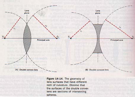
A spherical lens usually has two centers of curvature-the centers of the spheres that form the lens surfaces. These centers of curvature determine the principal axis of the lens. The radii of curvature of the two surfaces of double convex and double concave lenses are not necessarily equal, although they are so drawn in the ray diagrams in this chapter. The geometry of lens surfaces having different radii of curvature is shown in Figure 14-14.
4.7 Ray Diagrams The nature and location of the image formed by a lens is more easily determined by a ray diagram than by a wavefront diagram. The plane waves of Figure 14-13 can be represented by light rays drawn perpendicular to the wave fronts. Since these wave fonts approaching the lens are shown parallel to the lens plane, their ray lines are parallel to the principal axis of the lens.
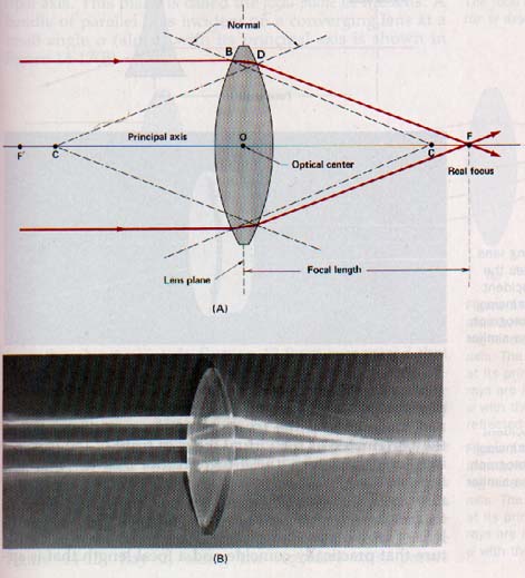
Observe that the principal axis passes through the center of the lens and is perpendicular to the lens plane. In Figure 14-15(A) these parallel rays (which are also parallel to the principal axis) are shown incident on a converging lens. They are refracted as they pass through the lens, and they converge at a point on the principal axis that locates the principal focus F of the lens.
At point B the incident ray is refracted toward the normal drawn to the front surface of the lens. At point D the incident ray is refracted away from the normal drawn to the back surface of the lens.
Because the rays of light actually pass through the principal focus F, it is called the real focus. Real images are formed on the same side of the lens as the real focus.
Had these rays approached the lens from the right parallel to the principal axis
Rays parallel to the principal axis are shown incident on a diverging lens in Figure 14-16(A). The rays of light are refracted as they pass through the lens and diverge as they had originated at the principal focus F' located at i front of the lens. Because the rays do not actually pass through this principal focus, it is called a virtual focus. Virtual images are formed on the same side of the lens as virtual focus.
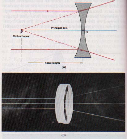
Figure 14-16. The diverging lens. (A) A ray diagram illustrates the refractive divergence of incident light rays parallel to the principal axis of the lens. (B) A photograph using light pencils shows a similar divergence.
In general, lenses refract rays that are parallel to the principal axis and the refracted rays either converge at the real focus behind the (converging) lens or diverge as if they originated at the virtual focus in front of the (diverging) lens.
However, these foci are not midway between the lens ana the center of curvature as they are in spherical mirrors. The positions of the foci on the principal axis depend on the index of refraction of the lens.
A common double convex lens of crown glass has principal foci and centers of curvature that practically coincide and a focal length that is approximately equal to its radius of curvature.
The focal length, f, of a lens is the distance between the optical center of the lens and the principal focus.
The focal length of any lens depends on its index of refraction and the curvature of its surfaces. The higher its index of refraction, the shorter is its focal length. The longer its radius of curvature, the longer is its focal length.
A "bundle" of parallel light rays incident on a converging lens parallel to its principal axis is refracted and converges at the principal (real) focus behind the lens. The image is ideally a point of light at the real focus. This refraction is shown in Figure 14-17(A).
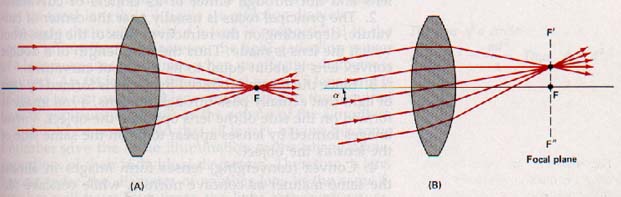
Bundles of parallel rays are not always incident on a lens parallel to its principal axis. If such rays are incident on a converging lens at a small angle with the principal axis, they converge at a point in the plane that contains the principal focus of the lens and is perpendicular to the principal axis.
This plane is called the focal plane of the lens. A bundle of parallel rays incident on a converging lens at a small angle (alpha) with its principal axis is shown in Figure 14-17(B).
14.8 Images by Refraction The image of a point on an object is formed by intersecting refracted rays emanating from the object point. In Section 13.8 we recognized that the task of locating graphically an image formed by reflection is simplified if we select incident rays that have 'known' paths after reflection.
These rays, called principal rays, are shown with their reflected paths in Figure 13-17. Their paths after refraction are also known. They are shown with their refracted paths in Figure 14-18.

The image S' of point S (the object in Figure 14-18) is formed by the converging lens when the refracted rays from point S intersect behind the lens. Ray 1, parallel to the principal axis, is refracted through the real focus, F. See Figure 14-15. Ray 2, along the secondary axis, passes through the Optical center of the lens, 0, without appreciably refracted.
Ray 3 passes through the focus, F', and is refracted parallel to the principal axis. The three refracted rays intersect at the image point S'. Observe that any two of the principal rays emanating from same object point are able to locate the image of that point.
Lenses and mirrors differ in several ways.
1. Secondary axes pass through the optical center of a lens and not through either of its centers of curvature.
2. The principal focus is usually near the center of curvature, depending on the refractive index of the glass from which the lens is made. Thus the focal length of a double convex lens is about equal to its radius of curvature.
3. Since the Image produced by a lens is formed by rays of light that actually pass through the lens, a real image is formed on the side of the lens opposite the object. Virtual images formed by lenses appear to be on the same side of the lens as the object.
4. Convex (converging) lenses form images in almost the same manner as concave mirrors, while concave (diverging) lenses are like convex mirrors in the manner in which they form images.
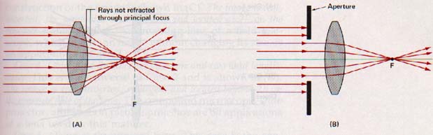
Spherical lenses, like spherical mirrors, have aberration defects . See Figure 14-19. When such lenses are used with large apertures, images formed by rays passing through the central zones of the lens are generally sharp and well defined, while images formed by rays passing through the edge zones are fuzzy.
This defect of lens images is called spherical aberration.
Similarly, rays of light coming from an object point not on the principal axis are not brought to a sharp focus in the image plane. This defect of lenses is known as Iens astigmatism.
By using a combination of lenses of suitable refractive indexes and focal lengths, lens makers produce anastigmatic lenses. Such lenses give good definition over the entire image even when used with large apertures.
A lens of short focal length that can be used with a large aperture has a large light-gathering capability. It is said to be a "fast" lens.
The light-gathering power of a camera lens is given in terms of its f-number.
This number is determined by the focal length of the lens and its effective diameter. The effective diameter is the diameter of the camera aperture (diaphragm) that determines the useful lens area.
The light-gathering power, or "speed", of a lens is expressed as the ratio of its focal length to its effective diameter.
If the speed of a lens is given as f/4, it means that its focal length is 4 times its effective diameter. Because the useful area of a lens is proportional to the square of its effective diameter, the light-gathering power of a lens increases four times when its effective diameter is doubled.
An f/4 lens is 4 times as fast as an f/8 lens, and is 16 times as fast as an f/16 lens. It follows that the required time of exposure increases as the square of the f-number.
It should be recognized that all lenses having the same f-number give the same illumination in the image plane, regardless of their individual diameters. Therefore, a lens having twice the diameter of another lens of the same f-number will have four times the light-gathering power, but this light will be spread over an image having four times the area and will give the same image brightness.
14.9 Images Formed by Converging Lenses We shall consider six different cases of image formation. These cases are illustrated in Figure 14-20.
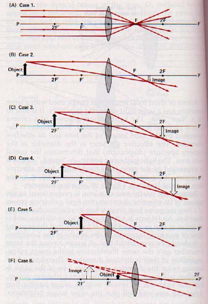
Case 1. Object at an infinite distance. The use of a small magnifying glass to focus the sun's rays upon a point approximates this first case. While the sun is not at an infinite distance, it is so far away that its rays reaching the earth are nearly parallel. When an object is at an infinite distance and its rays are parallel to the principal axis of the lens, the image formed is a point at the real focus. See Figure 14-20(A). This principle can be used to find the focal length of a lens by focusing the sun's rays on a white screen. The distance from the screen to the optical center of the lens is the focal length of the lens.
Case 2. Object at a Finite distance beyond twice the focal length. Case 2 is illustrated in (B). Rays parallel to the principal axis, along the secondary axis, and emanating from a point on the object are used to locate the corresponding image point. The image is real, inverted, reduced, and located between F and 2F of the opposite side of the lens. The lenses of the eye and the camera, and the objective lens of the refracting telescope are all applications of this case.
Case 3. Object at a distance equal to twice the focal length. The construction of the image is shown in (C). The image is real, inverted, the same size as the object, and located at 2F on the opposite side of the lens. An inverting lens of a field telescope, which inverts an image without changing its size, is an application of Case 3.
Case 4. Object at a distance between one and two focal lengths away. This is the converse of Case 2 and is shown in (D). The image is real, inverted, enlarged, and located beyond 2F on the opposite side of the lens. The compound microscope, slide projector, and motion picture projector are all applications of a lens used in this manner.
Case 5. Object at the principal focus. This case is the converse of Case 1. No image is formed, since the rays of light are parallel as they leave the lens (E). The lenses used in lighthouses and searchlights are applications of Case 5.
Case 6. Object at a distance less than one focal length away. The construction in (F) shows that the rays are divergent after passing through the lens and cannot form a real image on the opposite side of the lens. These rays appear to converge behind the object to produce an image that is virtual, erect, enlarged, and located on the same side of the lens as the object. The simple magnifier and the eyepiece lenses of microscopes, binoculars, and telescopes form images as shown in Case 6.
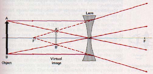
14.10 Images Formed by Diverging Lenses The only kind of image of a real object that can be formed by a diverging lens is one that is virtual, erect, and reduced in size. Diverging lenses are used to neutralize the effect of a converging lens, or to reduce its converging effect to some extent. The image formation is shown in Figure 14-21.
14.11 Object-Image Relationships For thin lenses, the ratio of object size to image size equals the ratio of object distance to image distance. This rule is the same as the rule for curved mirrors. Thus
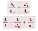
where h, and hi represent the heights of the object and image respectively, and do and di represent the distances of the object and image from the optical center the lens, and f the focal length.
The numerical value of the focal length f is positive for a converging lens and negative for a diverging lens. For real objects and images, the object and image distances d, and di have positive values. For virtual objects and images, do and di have negative values.
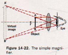
14.12 The Simple Magnifier A converging lens of short focal length can be used as a simple magnifier. The lens is placed slightly nearer the object than one focal length and the eye is positioned close to the lens on the opposite side. Ah, Sherlock Holmes.
This is a practical example of Case 6; the image is virtual, erect, and enlarged as shown in Figure 14-22.
A reading glass, a simple microscope, and an eyepiece lens of a compound microscope or telescope are applications of simple magnifiers.
Magnification M is simply the ratio of the image height to the object height.
M = di/do
Suppose an object is viewed by the unaided eye. As it is moved closer and closer to the eye, the image formed on the retina becomes larger and larger. Eventually, a nearest point is reached for the object at which the eye can still form a clear image.
This minimum distance for distinct vision is approximately 25 cm from the eye. Although this nearest point varies among individuals, 25 cm is taken as the standard distance for most distinct vision; it is called the near point.
As a person grows older the muscles of the eye, which thicken the lens and thus increase its convergence (shorten its focal length), gradually weaken. Consequently the near point moves out with aging.
If a converging lens is placed in front of the eye as a simple magnifier, the object can be brought much closer and the eye focuses on the virtual image. When the lens is used in this way, the object is placed just inside the principal focus (do = f). The image is then formed approximately at the near point.
Magnification, shown above to be equal to the ratio di/do can now be expressed for a simple magnifier as the ratio of the distance for most distinct vision to the focal length of the lens.
When f is given in centimeters, the magnification becomes approximately
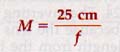
Magnifiers are labeled to show their magnifying power. Thus a magnifier with a focal length of 5 cm would be marked 5X. One with a focal length of 2.5 cm would be marked 10X, etc. Observe that the shorter the focal length of a converging lens, the higher is its magnification.
14.13 The Microscope The compound microscope, thought to be invented in Holland by Zacharias Janssen about 1590, uses a lens, the objective, to form an enlarged image as in Case 4.
This image is then magnified, as in Case 6, by a second lens, called the eyepiece. In Figure 14-23 a converging lens is used as the objective, with the object AB just beyond its focal length. At A'B', a distance greater than twice the focal length of the objective lens, an enlarged, real, and inverted image is formed. The eyepiece lens acts as a simple magnifier to enlarge this image.
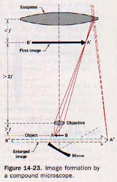
The magnifying power of the objective is approximately equal to the length of the tube, l, divided by the focal length, fo of the objective, or l/fo. The magnifying power of the eyepiece, acting as a simple magnifier, is approximately 25 cm/f,. The total magnification is the product of the two lens magnifications.
14.14 Refracting Telescopes A refracting astronomical telescope has two lens systems. The objective lens is of large diameter so that it will admit a large amount of light. The objects to be viewed in telescopes are always more distant than twice the focal length of the objective lens. As a consequence the image formed is smaller than the object. The eyepiece lens magnifies the real image produced by the objective lens.
The lenses of a terrestrial, or field, telescope form images just as their counterparts do in the refracting astronomical telescope.
Since it would be confusing to see objects inverted in a field telescope, another lens system is used to reinvert the real image formed by the objective. This additional inverting lens system makes the final image erect, as shown in Figure 14-24.
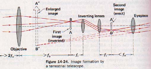
The inverting lens system does not magnify the image because the lens system is placed ex
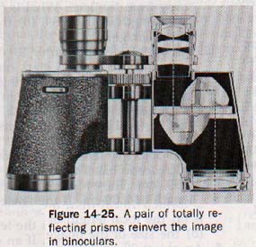
The prism binocular is actually a double field telescope that uses two sets of totally reflecting prisms instead of a third lens system to reinvert the real images formed by the objective lenses. This method of forming final images that are upright and correctly oriented also has the effect of folding the optical path, thus making binoculars more compact and easier to use than telescopes.
The prism binocular customarily has descriptive markings stamped on its case, such as 7 x 35, 8 x 50, etc. The first number gives its magnification, and the second number gives the diameters (in mm) of its objective lenses.
DISPERSION
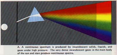
14.15 Dispersion by a Prism Suppose a narrow beam of sunlight is directed onto a glass prism in a darkened room. If the light that leaves the prism falls on a white screen, a band of colors is observed, one shade blending gradually into another.
This band of colors produced when sunlight is dispersed by a prism is called a solar spectrum.
The dispersion of sunlight was described by Newton, who observed that the spectrum was "violet at one end, red at the other, and showed a continuous gradation of colors in between."
We can recognize seven distinct colors in the visible spectrum. These are red, orange, yellow, green, blue, indigo and violet. Each color gradually blends into the adjacent colors giving a continuous spectrum over the range of visible light. A continuous visible spectrum is shown here:
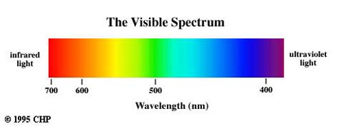
Light consisting of several colors is called polychromatic light; light consisting of only one color is called monochromatic light. All colors of the spectrum are present in the incident beam of sunlight. White light is a mixture of these colors.
The dispersion of light by a prism is shown in Plate I of the color insert"
It is evident that the refraction of red light by the prism is not as great as that of violet light; the refractions of other colors lie between these two. Thus the index of refraction of glass is not the same for light of different colors. If we wish to be very precise in measuring the index of refraction of a substance, monochromatic light must be used and the monochrome color must be stated.
14.16 The Color of Light A hot solid radiates an appreciable amount of energy that increases as the temperature is raised. At relatively low temperatures, the energy is radiated only in the infrared region. As the temperature of the solid is raised, some of the energy is radiated at higher frequencies.
These frequencies range into the red portion of the visible spectrum as the body becomes "red hot." At still higher temperatures the solid may be "white hot" as the major portion of the radiated energy shifts toward the higher frequencies.
Suppose we have a clear-glass tungsten-filament lamp connected in an electric circuit so that the current in the filament, and thus the temperature of the filament, can be controlled. A small electric current in the filament does not change the filament's appearance. As we gradually increase the current, however, the filament begins to with a dark red color.
To produce this color electrons the atoms of tungsten must have been excited to high energy levels so that upon de-excitation emit energy with wavelengths of about 7600 A.
Even fore the lamp filament glows visibly, experiments that it radiates infrared rays that can be detected. As the current is increased further, the lamp gives off orange light in addition to red, then the adds yellow, and finally at higher temperatures it enough other colors to produce white light.
A photographer's tungsten-filament flood lamp radiates at a very high temperature. If the white light of such lamp is passed through a prism, a band of colors similar the solar spectrum is obtained. Figure 14-26 shows the distribution of radiant energy from an "ideal" radiator several different temperatures.
Considering the wavelengths of various colors shown in Plate I, it is evident that our eyes are sensitive to a range of frequencies equivalent to about one octave.
The wavelength of the light at the upper limit of visibility (7600 A) is about twice the wavelength of the light at the lower limit of visibility (4000 Bi). We use the word color to describe a psychological sensation through the visual sense related to the physical stimulus of light. The color perceived for monochromatic light depends on the wavelength of the light. For example, when light of about 6500 A enters the eye, the color perceived is red.
14.17 The Color of Objects Color is a property of the light that reaches our eyes. Objects may absorb certain wavelengths from the light falling upon them and reflect other wavelengths.
For example, a cloth that appears blue in sunlight appears black when held in the red portion of a solar spectrum in a darkened room. A red cloth held in the blue portion of the solar spectrum also appears black. The color of an opaque object depends upon the frequencies of light it reflects. If all colors are reflected, we say it is white. It is black if it absorbs all the light that falls upon it. It is called red if it absorbs all other colors and reflects only red light.
The energy associated with the colors absorbed is taken up as heat.
A piece of blue cloth appears black in the red portion of the spectrum because there is no blue light there for it to reflect and it absorbs all other colors. For the same reason, a red cloth appears black in the blue portion of the spectrum. The color of an opaque object depends on the color of the light incident upon if.
Ordinary window glass, which transmits all colors, is said to be colorless. Red glass absorbs all colors but red, which it transmits. The stars of the United States flag would appear red on a black field if viewed through red glass. The color of a transparent object depends upon the color of the light that it transmits.
14.18 Complementary Colors Because polychromatic light can be dispersed into its elementary colors, it is reasonable to suppose that elementary colors can be combined to form polychromatic light. There are three ways in which this can be done.
1. A prism placed in the path of the solar spectrum formed by another prism will recombine the different colors to produce white light. Other colors can be compounded in the same manner.
2. A disk that has the spectral colors painted on it can be rotated rapidly to produce the effect of combining the colors. The light from one color forms an image that persists on the retina of the eye until each of the other colors in turn has been reflected to the eye. If pure spectral colors are used in the proper proportion, they will blend to produce the same color sensation as white light.
3. Wavelengths from the middle region of the visible spectrum combined with wavelengths from the two end regions produce white light. This method is described in Section 14.19.
Two prisms are used as described above, but with the red light from the first prism blocked off from the second prism.
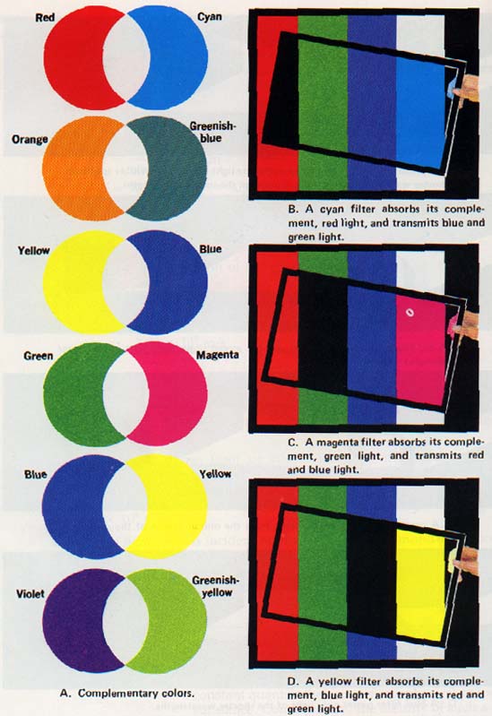
Red light and cyan should therefore combine to produce white light, and a rotating color wheel shows this to be true. Any two colors that combine to form white light are said to be complementary.
In similar fashion it can be shown that blue and yellow are complementary colors. White fabrics acquire a yellowish color after continued laundering. A blue dye added to the laundry detergents neutralizes the yellow color and fabrics appear white.
Iron compounds in the sand used making glass impart a green color to the glass. Manganese gives glass a magenta, or purplish-red, color. However, if both these elements are present in the right proportion the resulting glass will be colorless. Green and magenta are complementary colors. The complements of the seven elementary spectral colors are shown in Plate II.
Plate II
14.99 The Primary Colors The six regions of color in the solar spectrum are easily observed by the dispersion sunlight. Further dispersion within a color region fails reveal any other colors of light.
We generally identify range of wavelengths comprising a color region by color of light associated with that region. These are the elementary colors of the visible spectrum; they combine produce white light. However, the complement of an elementary color is not monochromatic but is a mixture of of the elementary colors remaining after the one elementary color has been removed.
Experiments with beams of different colored lights have shown that most colors and hues can be described in terms of three different colors. Light from one end of visible spectrum combined with light from the middle region in various proportions will yield all of the color in the half of the spectrum that lies in between them.
Light from the opposite end, when combined with light the middle region, will also yield all hues in the half of spectrum that lies in between them.
Colored light from two end regions and the middle region can be combined match most of the hues when mixed in the proper proportions. The three colors that can be used most successfully in color matching experiments of this sort are red, green, and blue. Consequently these have been called the primary colors.
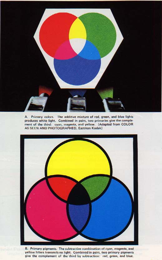
Suppose we project the three primary colors onto white screen as shown in Plate III(A) below. The three beams can be adjusted to overlap, producing additive mixtures of these primary colors.
Observe that green and blue light combine to produce cyan, the complement of red, green and red lights combine to produce yellow, the complement of blue; and red and blue lights combine to produce magenta, the complement of green.
Thus two primary colors combine to produce the complement of the third primary color.
Where the three primary colors overlap, white light is produced.
14.20 Mixing Pigments When the complements blue are mixed, white light results by an additive process. If we mix a blue pigment with a yellow pigment, a green mixture results.
This process is subtractive since each pigment subtracts or absorbs certain colors. For example, the yellow pigment subtracts blue and violet lights and reflects red, yellow, and green.
The blue pigment subtracts red and yellow lights and reflects green, blue, and violet. Green light is the only color reflected by both pigments; thus the mixture of pigments appears green under white light.
The subtractive process can be demonstrated by the use of various color filters that absorb certain wavelengths and transmit others from a single white-light source. When pigments are mixed, each one subtracts certain colors from white light, and the resulting color depends on the light waves that are not absorbed.
The primary pigments are the complements of the three primary colors. They are cyan (the complement of red), magenta (the complement of green), and yellow (the complement of blue). When the three primary pigments are mixed in the proper proportions, all the colors are subtracted from white light and the mixture is black. See Plate III(B).
14.21 Chromatic Aberration Because a lens configuration has some similarity to that of a prism, some dispersion occurs when light passes through a lens. Violet light is refracted more than the other colors and is brought to a focus by a converging lens at a point nearer the lens than the other colors. Because red is refracted the least, the focus for the red rays is farthest from the lens.
Figure 14-27(A).
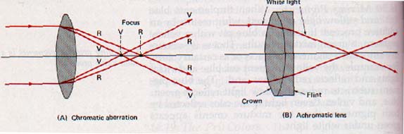
Thus images formed by ordinary spherical lenses are always fringed with spectral colors. The nonfocusing of light of different colors is called chromatic aberration.
Sir Isaac Newton developed the reflecting telescope to avoid the objectionable effects of chromatic aberration that occur when observations are made through a refracting telescope.
The English optician John Dalton (1706-1761) discovered that the fringe of colors could be eliminated by means of a combination of lenses. A double convex lens of crown glass used with a suitable plano-concave lens of flint glass
SUMMARY
The laws of refraction describe the behavior of light rays that pass obliquely from one medium into another of different optical density. The index of refraction of any transparent material is defined in terms of the speed of light in a vacuum and the speed of light in the material.
The index of refraction is also expressed in terms of Snell's law. Total reflection is explained on the basis of critical angle of a material and the limiting value of the angle of refraction. Converging lenses have convex and form images in a manner similar to that of concave mirrors. Diverging lenses have concave surfaces and form images in a manner similar to that of convex mirrors.
The general lens equations correspond to those for curved mirrors. These relate object and image sizes their respective distances from the lens and object and image distances with focal length of the lens.
A converging lens forms either real or virtual images of real objects depending the position of the object relative to the principal focus of the lens.
A diverging lens forms only virtual images of real lens functions in common types refractive instruments such as microscopes and telescopes can be analyzed by each lens separately. Sunlight is composed of polychromatic light that undergoes dispersion when refracted by a prism. Seven elementary colors are recognized in dispersed white light. ROYGBIV.
The visual perception of color is related to the wavelength of visible light. The removal of an elementary color from white light leaves a polychromatic color that is the complement of the color removed.
Addition of complementary colors produces white light. White light is produced by adding the primary colors. Any two of the three primary colors will combine to produce the complement of the third.
The primary pigments are complements of the primary colors. Their combination is considered to be a subtractive process.
VOCABULARY
achromatic lens, angle of incidence, angle of refraction, chromatic aberration, complementary colors, converging lens, critical angle, diverging lens, elementary color, eyepiece, focal length, focal plane, index of refraction, lens equation, monochromatic, near point, objective, optical density, polychromatic, primary color, primary pigment, principal axis principal focus principal ray, real focus, real image, refraction, refractometer, secondary axis, Snell's law, solar spectrum, spherical aberration, total refraction, virtual focus, virtual image.
Ah Yaz Indeed!
 Assignment Sheet for this Research Text Only.
 Go to Textbook Assignments for Portfolio:
.................................First Semester
.................................Second Semester