Reflection of Light
Reflection of Light
The purpose of this is to give quick reference to information or to use in an emergency (like if your text has accidentally been left under your desk at school).
This is NOT intended to replace reading the text with its excellent photographs, diagrams, charts, and tables.
REFLECTION
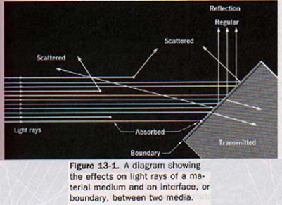
13.1 Reflectance A light beam passing through any material medium will become progressively weaker due to two effects.
Part of the light beam's energy will be absorbed by molecules of the medium and part will be scattered in all directions by the molecules.
A light beam striking the boundary between two media can be partly transmitted and partly returned to the first medium. See Figure 13-1.
Light returned to the first medium is said to be reflected at the boundary. Reflection is described as a wave property in Section 10.10.
Part of the reflected light proceeds in a common direction but part can be reflected in all possible directions as scattered light. See Figure 13-2 for these effects.
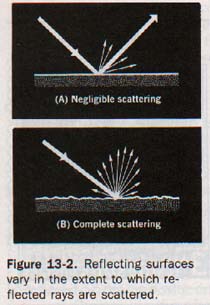
The fact that a portion returns in a common direction provides us with a method for controlling the reflection of a light beam.
The amount of light reflected at the surface of an object, whether by scattering or by unidirectional reflection, depends on the kind of material underlying the surface, the smoothness of the surface, and the angle at which the light strikes it.
The ratio of the light reflected from a surface to the light falling on the surface is called reflectance. This ratio is commonly expressed as a percentage. Materials differ widely in their reflectance. The material of highest reflectance is magnesium oxide, a white chalky substance that reflects about 98% of incident light with practically complete scattering.
The reflectance of a smooth surface of silver is about 95% with negligible scattering. Some black surfaces have reflectances of 5% or less.
13.2 Regular and Diffused Reflection The reflection of sunlight by a mirror produces a blinding glare. The rays of the sun reaching the earth are practically parallel and thus have the same angle of incidence. They remain practically parallel after being reflected from a plane mirror. Such reflection, in which scattering of the reflected rays is negligible, is called regular reflection.
Polished, or specular, surfaces cause regular reflection and the image of the luminous source is sharply defined. The regular reflection of a narrow beam of light is in one direction with no appreciable loss of definition or intensity. The nature of regular reflection is shown in Figure 13-3.
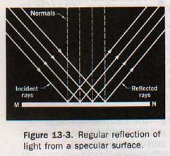
Regular reflection from highly polished surfaces provides for relatively accurate control of light rays. Searchlights, beacons, and automobile spotlights use concentrated light sources of high intensity and highly polished regular reflectors to redirect light rays in the desired direction.
In Figure 13-4 we observe what happens to a beam of light incident on an irregular surface.
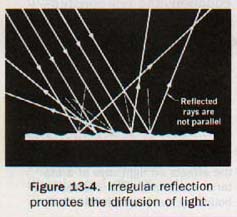
The laws of reflection hold true for each particular ray of light, but the normals to the surface are not parallel and the light is reflected in many directions. Such scattering, or diffusion, of light is extremely important.
If the sun's rays were not diffused by rough and irregular surfaces and by dust particles in the air, the corners of a room and the spaces under shade trees would be in almost total darkness and the glare would be dazzling in sunlit areas.
Astronauts have found that it is possible for them to see in the shadows on the lunar surface where there is no air, but they cannot see as easily as we can on the surface of the earth.
13.3 Mirrors as Reflectors The reflection of light is similar to the reflection of sound or to the rebound of an elastic ball. The line MN in Figure 13-5(A) represents a reflecting surface; AD is a ray of light incident upon the reflector at D; DB is the path of the reflected ray.
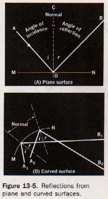
The line CD, perpendicular to the reflecting surface at the point of incidence, is called a normal.
In Figure 13-5(B) the normal is perpendicular to the tangent to the curved reflecting surface at the point of incidence. Recall from Section 10.10 that the angle of incidence (i) is the angle between the incident ray and the normal at the point of incidence [angle ADC in Figure 13-5(A)1.
In Chapter 10 we examined the nature of reflection by sending water waves against a barrier in the ripple tank. At that time we recognized the first law of reflection:
The angle of incidence, i, is equal to the angle of reflection, r. The angle of reflection, r, is the angle between the reflected ray and the normal at the point of incidence [angle BDC in Figure 13-5(AD.
The relationships between an incident ray of light and the reflected ray and between the angles they form with the normal are easily determined in the laboratory. Critical observation of the specular reflection of light reveals a second law of reflection:
The incident ray, the reflected ray, and the normal to the reflecting surface lie in the same plane.
As mentioned in Section 10.10, these laws are true for all forms of wave propagation.
Any highly polished surface that forms images by the regular reflection of light can act as a mirror. A plane mirror of plate glass is silvered on one surface to reflect the light efficiently. Its reflectance may be nearly 100%. The plane parallel surfaces of the plate glass allow an essentially distortion-free image to be observed.
A spherical mirror is a small section of the surface of a sphere. One side of the section is polished or coated with a reflective material. When viewed from the inside, the mirror is called a concave mirror, as indicated in Figure 13-6(A).
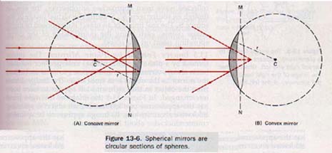
When viewed from the outside, it is called a convex mirror, as indicated in Figure 13-6(B).
The laws of reflection hold for both spherical mirrors and plane mirrors. However, the size and position of the images formed by spherical mirrors are quite different from the size and position of images formed by plane mirrors.
13.4 Images by Reflection Light rays reflected from a concave mirror may meet in front of the mirror and form an image of the object from which the light comes. Such an image can be projected on a screen placed at the image location. An image formed by converging rays of light actually passing through the image point is called a real image. Real images are inverted relative to the object and can be larger or smaller than the object.
Your image observed in a plane mirror seems to be behind the mirror, although the rays forming it actually are reflected forward from the mirror surface. This image is called a virtual image.
Rays of light that appear to have diverged from the image point do not actually pass through that point. Virtual images cannot be projected on a screen. They are erect with respect to the object and can be enlarged or reduced in size.
In Figure 13-7 light traveling from a point source in spherical wave fronts is reflected from a plane mirror.
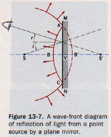
At the instant that points A and C on the wave front reach the mirror, point B has been reflected back towards the source at S, having traveled the distance VB. The reflected wave front ABC has an apparent source S' at an apparent distance VS' behind the mirror.
Note that VS' is equal to the distance VS of the source in front of the mirror. The reflected wave front approaches an observer, the eye, as though its source were S', S' being the virtual image of the source S. The real image of an object is composed of many image points, each being the point image of the corresponding point on the object.
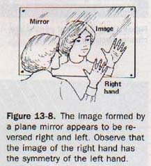
13.5 Images Formed by PIane Mirrors The image formed by a plane mirror is neither enlarged nor reduced but is always virtual, erect, and appears to be as far behind the mirror as the object is in front of it.
The image differs from the object in that right and left appear to have been interchanged. In Figure 13-8 the image of the right hand has the appearance of a left hand. If an object is spinning clockwise about its axis, its image appears to be spinning counterclockwise about its image axis.
The ray diagram in Figure 13-9 shows a simple graphical method of locating the image formed by a plane mirror. The triangle ABC, drawn on paper, is used as the object in front of a mirror, MN.
A pin is placed at each vertex of the triangle. Rays A01 and AO2 from pin A strike the mirror so as to be reflected to the two eyes, El and EP of the observer. When the sight lines ElOl and E202 are produced (extended) behind the mirror, they intersect at A', which is the location of the image of pin A.
A comparison of triangles A0201 and A10201 makes it apparent that A' is as far behind the mirror as A is in front of it. The images of B and C are located in similar fashion at B' and C'.
In each instance the image appears to be as far behind the mirror as the abject is in front of it. When the image points A'B'C' are joined, it becomes evident that the image is the same size as the object.
This method of constructing images is based on the laws of reflection. The light ray A01 is reflected at point 01 and is sighted at El.
By drawing a normal to the mirror at 01, the angle AOlEl is bisected and the angle of reflection ElOlR is equal to the angle of incidence AO1R. The incident ray A01, the reflected ray 01E1, and the normal 01R all lie in the same plane.
Sound waves bound and rebound between parallel cliffs or walls and produce multiple echoes. In a similar fashion, light reflects back and forth between parallel mirrors or mirrors set at an acute angle and forms multiple images.
The image formed in one mirror appears to act as the object forming the image in the next mirror. Because some light energy is absorbed and some is scattered at each mirror, the succeeding images become fainter.
A thick plate glass mirror produces multiple reflection, as shown in Figure 13-10, because some light is reflected each time a boundary is encountered.
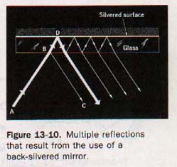
Multiple reflections can be avoided by aluminizing or silvering the front surface of a glass mirror. Mirrors for astronomical telescopes and other precision instruments are usually coated with aluminum in this manner. Such reflecting surfaces are exposed and can be easily damaged.
13.6 Curved-Mirror Terminology In order to discuss image formation by spherical mirrors, several terms associated with this process must be identified. In this discussion, reference is made to the diagrams of mirrors shown in Figures 13-11 and 13-12.
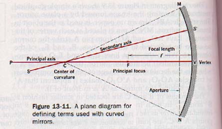
The arc MVN is the portion of the spherical surface separated from the sphere by a cutting plane represented by the line MN.
1. The center of curvature, C, is the center of the original sphere. The radius of the sphere is also the radius CV of the spherical mirror.
2. The vertex, V, is the center of the mirror.
3. The principal axis of the mirror is the line PV drawn through the center of curvature and the vertex.
4. A secondary axis is any other line drawn through the center of curvature to the mirror: SS', for example.
5. A normal to the surface of a spherical mirror is a radius drawn from the point of incidence of a light ray. Therefore the normal is perpendicular to the mirror surface at the incidence point. (Normals are illustrated in Figure 13-12.)
6. The principal focus, F, is the point on the principal axis where light rays close to and parallel to the principal axis converge, or from which they appear to diverge.
7. The focal length, f, is the distance from the vertex of the mirror to its principal focus.
8. The aperture determines the amount of light intercepted by the mirror. The length MN is called the linear aperture of the mirror, and the angle MCN is called the angular aperture. For a spherical mirror to be capable of forming sharp images, its aperture must be small compared with its focal length.
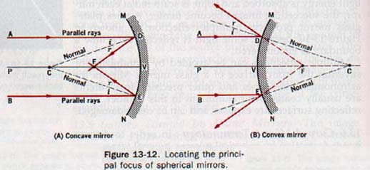
13.7 Rays Focused by Spherical Mirrors In Figure 13-12(A) the rays AD and BE, parallel to the principal axis, are shown incident on a concave spherical mirror at points D and E respectively.
The normals CD and CE are drawn to the points of incidence. By the second law of reflection, the reflected rays converge on the principal axis at F, the principal focus.
Because the incident rays converge upon being reflected, concave mirrors are also known as converging mirrors.
The distance FV is the focal length of the mirror. For spherical mirrors of small aperture, the focal length is one-half the radius of curvature.
Parallel rays incident on the surface of a convex spherical mirror are shown in Figure 13-12(B). The normals CD and CE produced beyond the mirror surface show the reflected rays to be divergent along the lines FD and FE produced, F being the principal focus of the mirror.
Rays parallel to the principal axis appear to diverge from the principal focus of a convex mirror. Because incident rays diverge on being reflected, convex mirrors are known as diverging mirrors.
Diverging rays from a point S incident on a concave mirror, Figure 13-13, converge to a focus at some point S' beyond the principal focus of the mirror.
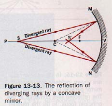
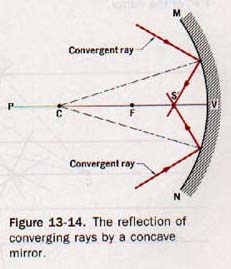
If S is located on the principal axis, the image S' is also on the principal axis. Suppose the source of diverging rays is now moved to position S'. The image formed by the mirror will be at S. Converging rays are also focused by concave mirrors.
As shown by Figure 13-14, the point of focus is between the vertex and the principal focus.
In every instance the direction of a reflected ray is determined by the laws of reflection.
As observed in Figure 13-12(A), the incident parallel rays that are also parallel to the principal axis of the concave mirror are reflected and converge at the principal focus.
The image is ideally a point of light at the principal focus. If the parallel rays are not parallel to the principal axis but are incident at a small angle with the principal axis, they do not converge at the principal focus. Instead they are focused at a point in a plane that contains the principal focus and is perpendicular to the principal axis.
This plane is called the focal plane of the mirror.
Figure 13-15 illustrates the reflection of a bundle of parallel light rays incident on a concave mirror. In Figure 13-15(A) the rays are parallel to the principal axis of the mirror, and in
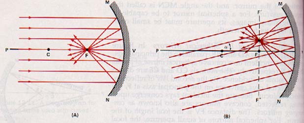
Figure 13-15. In (A) parallel rays are shown incident on a concave mirror parallel to its principal axis. The reflected rays converge at the principal focus. In (B) the parallel rays are incident at a small angle a (alpha) with the principal axis. Here the reflected rays are focused at a point in the focal plane F'F of the mirror.
Figure 13-15(B) the rays are at a small angle a (the Greek letter alpha) with the principal axis.
If the aperture of a spherical mirror is large, the parallel rays of light striking the mirror near its edge are not reflected through the principal focus but are focused at points nearer the mirror, as shown in Figure 13-16(A). Only those parallel rays that are incident on the mirror near its vertex are reflected to the principal focus. This characteristic of spherical mirrors of large aperture is known as spherical aberration and results in the formation of fuzzy images.
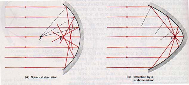
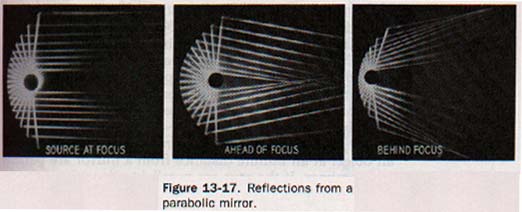
In order to reduce spherical aberration, the aperture of the spherical mirror must be small. For angular apertures no larger than about 10o, the distortion of the image is negligible. Spherical aberration can be avoided for parallel rays if the mirror surface is made parabolic instead of spherical. See Figure 13-16(B).
The parabolic mirror shown in Figure 13-17 reflects light rays originating at the focus as parallel rays. Parabolic reflectors are used in automobile headlights, microwave communication relays, radar, and radio telescopes. Parabolic mirrors are also used in large reflecting telescopes to collect and focus light rays from distant objects.
13.8 Constructing the Image In Figure13-18 the image of point S formed by a concave mirror is to be located.
First the principal axis PV is drawn through C. Because light is given off in all directions from point S, any two lines can be drawn from S to represent rays of light incident on the mirror. The point of intersection of the reflected rays locates the image of S at S'. The construction is greatly simplified if the incident rays are selected for which the directions of the reflected rays are known from the geometry of the system.
Three such rays are shown in Figure 13-18.

Ray SA, parallel to the principal axis, is reflected through the principal focus. Ray SB passes through the principal focus and is reflected parallel to the principal axis. Ray SC lies along the secondary axis. It is reflected back along its path of incidence because the angle of incidence is zero. Note That the convergence of two af these three reflected rays at a common point S' forms image of S.
If the object were located at S' the image would b( formed at S. The object and image are thus interchangeable, or conjugate. The positions of the object and its image, S and S', are called conjugate points.
13.9 Images Formed by Concave Mirrors The image formed by a concave mirror can be constructed by locating the images of an adequate number of object points.
Suppose the object is an arrow. The entire image can be located by constructing the image points of the head and the tail of the arrow.
Concave mirror images can be grouped into six cases based on the position of the object in front of the mirror.
Case 1. Object at an infinite distance. Rays emanating from an object at an infinite distance from a mirror are parallel at the mirror. If the rays are parallel to the principal axis, they are reflected through the principal focus. See Figure 13-19(A).
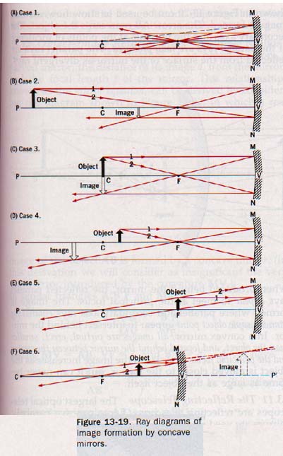
We therefore conclude that the image formed by a concave mirror of an object an infinite distance away is a point at the principal focus.
The rays of the sun reaching the earth are practically parallel and provide a simple method for finding the approximate focal length of a concave mirror.
Case 2. Object at a finite distance beyond the center of curvature. In Figure 13-19(B) the image of the object arrow can be located using the method illustrated in Section 13.8.
Two known rays, 1 and 2, emanating from the head of the arrow, intersect after reflection to locate the image of the arrowhead. The image of the tail lies on the principal axis as shown earlier in Figure 13-13.
The image in this case is real, inverted, reduced in size, and located between the center of curvature and the principal focus.
The nearer the object approaches the center of curvature, the larger the image becomes and the nearer the image approaches
C. Case 3. Object at the center of curvature. When the object arrow is at the center of curvature, as shown in Figure 13-19(C), the image of the arrowhead is found inverted at C. When the object is at the center of curvature, the image is real, inverted, the same size as the object, and located at the center of curvature.
Case 4. Object between the center of curvature and principal focus. This case is the converse of Case 2 and is shown in Figure 13-19(D).
The image is real, inverted, enlarged, and located beyond the center of curvature. The nearer the object approaches the principal focus of the mirror, the larger the image becomes and the farther it is beyond C.
Case 5. Object at principal focus. This case is the converse of Case 1; all rays originating from the same point on the object are reflected from the mirror as parallel rays. See Figure 13-19(E).
When the object is at the principal focus, no image is formed. If the object is a point source, all reflected rays are parallel to the principal axis.
Case 6. Object between principal focus and mirror. The reflected rays from any point on the object are divergent; they can never meet to form a real image. They appear to meet behind the mirror, however, to form a virtual image as shown in Figure 13-19(F). In this case, the image is virtual, erect, enlarged, and located behind the mirror.
13.10 Images Formed by Convex Mirrors A convex mirror forms an erect image of reduced size. The diagram shown in Figure 13-20 can be used to show how such image is formed.
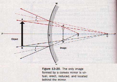
The arrow AB represents the object. secondary axes and the normals at the points of incidence of the parallel rays are radii produced. The parallel rays reflected from the surface of the mirror as divergent
When produced behind the mirror, the reflected parallel rays appear to meet at the principal focus. The image is formed where parallel and secondary-axis rays emanating from the same object point appear to intersect behind the mirror.
In a convex mirror, all images are virtual, erect, smaller than the object, and located behind the mirror between the vertex and the principal focus.
The size of the image increases as the object is moved closer to the mirror, but it can never become as large as the object itself.
13.11 The Reflecting Telescope The largest optical telescopes are reflecting telescopes. Large concave parabolic mirrors are used to collect and focus light rays.
Reflecting telescopes can be made much larger than refracting (lens) telescopes. It is difficult to obtain a large piece of glass of sufficiently high optical quality for a lens, to grind and polish two surfaces with precision, and to support it appropriately.
When objects being viewed with a reflecting telescope are at a finite distance beyond the center of curvature of the mirror, Case 2 (Section 13.9) applies. The image is real, inverted, and located near the principal focus of the mirror. This real image can be reflected out of the path of the rays of light incident on the mirror so that it can be viewed or photographed from a position outside the telescope.
The inversion of the image is not objectionable when reflecting telescopes are used for astronomical viewing.
13.12 Object-lmage Relationships A simple relationship exists among the distance of an object d, from a curved mirror, the distance of its image di from the mirror, and the focal length f of the mirror. This relationship, known as the mirror equation, can be derived by considering the diagram shown in Figure 13-22, in which a real image where d, is the distance of the object from the mirror, di the image distance, and f the focal length of the mirror.
Equation 6, the mirror equation, is applicable to all concave and convex mirrors.
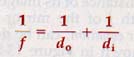
Where f is the focal length, do is the distance to the object, and di is the distance to the image.
When an object is located less than one focal length in front of a concave mirror, the image is virtual.
It appears to be located behind the mirror, and the image distance di is a negative quantity. In the case of convex mirrors, the radius of curvature is negative and the image is virtual.
Therefore, both the focal length f and the image distance di are negative quantities. For concave mirrors, the radius of curvature and the focal length are positive.
The image distance can be either positive or negative being positive for real images and negative for virtual images. The significance of these negative quantities is illustrated in the following example.
The relative heights of an object and its image formed by mirror depend on their respective distances from center of curvature of the mirror. This can be seen similar triangles ABC and A'B'C of Figure 13-22.
We can demonstrate that for mirrors of small aperture the relative heights of the object and image also depend on respective distances from the vertex of the mirror.
If height of object AB in Figure 13-22 is represented by h, the height of the image A'B' is represented by hi, 4 of Section 13.12 becomes

Where ho is the height of the object, hi is the height of the image, do is the distance of the object, and do is the distance of the image.
The sign conventions for spherical mirror computations the mirror equation are summarized as follows:
1. The numerical value of the focal length, f, of a concave mirror is positive.
2. The numerical value of the focal length, f, of a convex mirror is negative.
3. The numerical value of the real object distance, do, is positive.
4. The numerical value of the real image distance, di, is positive.
5. The numerical value of the virtual image distance, di, is negative.
SUMMARY
The amount of incident light reflected from the surface of an object depends on the composition of the object, the character of its surface, and the angle at which the light rays strike the surface.
The ratio of the reflected light to the incident light is known as reflectance.
The angle of refection and the angle of incidence are equal, and both lie in the same plane.
Images may be either real or virtual. Real images are inverted with respect to the object and can be projected onto a screen. Virtual images are erect and cannot be projected onto a screen.
Images formed by plane mirrors are virtual, erect, and the same size as the object.
Images formed by plane mirrors appear to be the same distance behind the mirror as the object is in front of the mirror.
Concave mirrors cause reflected rays of the mirror dependent upon the distance between the student and the mirror light to converge. These mirrors can form real images.
The size and position of an image are related to the size of the object and its position relative to the mirror.
A virtual image is formed by a concave mirror if the object is less than a focal length away from the mirror.
Convex mirrors cause reflected rays of light to diverge. They form virtual images of objects irrespective of the object distance from the mirror.
Spherical mirrors of large aperture form indistinct images.
The spherical-mirror defect responsible for fuzzy images is known as spherical aberration. Parabolic mirrors do not show this aberration defect.
When mirrors of large aperture are required, parabolic surfaces rather than spherical surfaces are used to reflect incident light.
VOCABULARY
angle of incidence, angle of reflection, angular aperture, aperture, concave, conjugate points, converge, convex, diffusion, diverge, focal length, focal plane, linear aperture, mirror equation, normal, plane mirror, principal axis, principal focus, real image, reflectance, regular reflection, scattering, secondary axis, specular, spherical aberration, spherical mirror, vertex, virtual image.
Ah Yaz Indeed!
 Assignment Sheet for this Research Text Only.
 Go to Textbook Assignments for Portfolio:
.................................First Semester
.................................Second Semester