The Nature of Waves

The Nature of Waves
The purpose of this is to give quick reference to information or to use in an emergency (like if your text has accidentally been left under your desk at school).
This is NOT intended to replace reading the text with its excellent photographs, diagrams, charts, and tables.
THE NATURE OF WAVES
Max Planck originated the quantum theory, which states that electromagnetic waves consist of individual packets of energy. The theories of Planck and of his contemporary, Albert Einstein, are among the most revolutionary ideas in twentieth-century physics. Planck received the Nobel Prize in 1918.
10.1 Energy Transfer The locations of energy sources are often different from the locations of energy requirements. Clearly, some mechanism must be provided for the transport of energy from one place to another. One way of transporting energy is by the movement of materials or objects.
Winds and projectiles in flight are well-known examples. When a baseball strikes a window, the glass is shattered by energy transferred from the ball during impact.
Thermal convection is a familiar process for transferring heat energy from one location to another by the gross movement of quantities of heated gas or liquid between these locations.
A more interesting but more complicated way of transporting energy involves waves. Several natural phenomena that exemplify waves can be recognized. These phenomena are studied collectively because of an important simplifying fact: the ideas and language used to describe waves are the same, regardless of the kinds of waves involved.
The basic concept in the use of the term wave is that the wave involves some quantity or disturbance that changes in magnitude with respect to time at a given location and changes in magnitude from place to place at a given time.
We shall recognize that some wave disturbances occur only in material media and others are not restricted in this way. In general, a wave is a disturbance that propagates through a medium or space. All kinds of waves are characterized by their transport of energy without the bulk transport of matter.
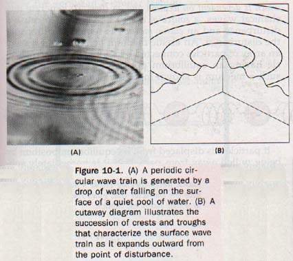
A stone, or a single drop of water, falling into a quiet pond produces the familiar wave pattern on the surface of the water shown in Figure 10-1.
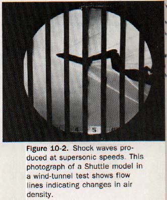
A sound is heard because a wave travels from the source through the intervening atmosphere. The energy released by a great explosion can shatter windows far from its source because a wave of compression moves out from the source in all directions. The "shock wave" of a sonic boom can have similar destructive effects. These waves are disturbances that move through a material medium.
We are able to explain some properties of light by means of waves. Physicists have demonstrated that light waves, radio waves, infrared and ultraviolet waves, X rays, and gamma rays are fundamentally similar.
They are electromagnetic waves. Although they can travel through matter, their transmission from one place to another does not require a material medium, that is, a medium composed of matter. The nature of electromagnetic waves will be discussed in detail in later chapters.
For the present (through Section 10.5) we shall be concerned with waves that require a material medium for their propagation. These waves are called mechanical waves. If the motion responsible for the wave disturbance is periodic, a periodic continuous wave, or wave train, is produced.
Such wave motion is related to harmonic motion. Harmonic motion is described in Section 5.10 in terms of a single object vibrating about its equilibrium position. Here, we must consider many particles vibrating about their respective equilibrium positions as the wave train travels through the medium. It is important to understand behavior of waves because the language and ideas of motion are needed to correctly describe the motions very small particles of matter.
As particles at some distance away from a source of vibrational energy are made to vibrate, their vibrations show that they have acquired energy. This energy has been transmitted to particles far from the energy source by the wave disturbance. Thus it is evident that waves provide a mechanism by which energy is transmitted from one location to another without the physical transfer of matter between these locations.
10.2 Mechanical Waves A mechanical wave is a disturbance in the equilibrium positions of matter, the magnitude of which is dependent on location and on time.
To generate mechanical waves, a source of energy is required to cause a disturbance and an elastic medium is required to transmit the disturbance. An elastic medium behaves as if it were an array of particles connected by springs with each particle having an equilibrium position. A simple model of such a medium is shown in Figure 10-3.
![]()
If particle 1 is displaced from its equilibrium position by being pulled away from particle 2, it is immediately subjected to a force from particle 2 that attempts to restore particle 1 to its original position. At the same time, particle 1 exerts an equal but opposite force on particle 2 that attempts to displace it from its equilibrium position.
Similar events occur but in opposite directions if particle 1 is displaced from its equilibrium position by being pushed toward particle 2.
Suppose particle 1 is displaced by an energy source. Then particle 1 exerts a force that displaces particle 2. Particle 2, in turn being displaced from its equilibrium position, exerts a force on particle 3, which is in turn displaced.
In this way, the displacement travels along from particle to particle. Because the particles have inertia, the displacements do not all occur at the same time but successively as the disturbance affects particles farther and farther from the source. The energy initially imparted to particle 1 by the energy source is transmitted from particle to particle in the medium without motion of the medium as a whole.
10.3 Transverse Waves A long spiral spring stretched between two rigid supports can represent an elastic medium, as shown in Figure 10-4(A).
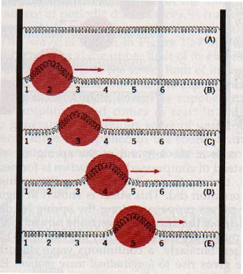
A portion of the spring is displaced at point 2 to form a crest, or upward displacement, as in Figure 10-4(B). To force the spring into this shape, point 2 must be pulled up while points 1 and 3 are held in place.
When the spring is released at points 2 and 3 simultaneously, point 2 accelerates downward and point 3 accelerates upward. The crest moves toward the right as in Figure 10-4(C).
Similarly, as the spring in the region of point 3 moves downward, the spring in the region of point 4 is displace upward.
In this manner the crest travels along the spring as shown in Figure 10-4(D) and (E). A trough, or downward displacement, formed at 2 travels along the spring in a similar fashion.
A single nonrepeated disturbance such as a single crest or a single trough is called a single-wave pulse or, simply, a pulse. The displacement of the particles of the medium (the coiled spring) caused by the pulse is perpendicular to the direction in which the pulse travels.
Such a pulse is said to be transverse. It is convenient to think of the crest as a positive pulse and the trough as a negative pulse. When a periodic succession of positive and negative pulses is applied to the coiled spring, a series of crests and troughs, called a continuous wave, or wave train, travels through the medium.
Again, the displacement of the particles of the medium is perpendicular to the direction the wave train travels. The wave disturbance is transverse. A transverse wave is one in which the displacement of particles the medium is perpendicular to the direction of propagation of wave.
10.4 Longitudinal Waves Suppose a similar spiral spring is used, but instead of pulling the spring out of line, several coils are pinched closer together at one end, as in Figure 10-5(A). Such a distortion is called a compression; When these compressed coils are released, they attempt to spread out to their equilibrium positions. Thus, they compress the coils immediately to the right and the compression moves toward the right. See Figure 10-5(B)-(D).
If the coils at the left end of the spring are stretched apart instead of compressed, a rarefaction is formed. When released, the rarefaction travels along the spring just as the compression did. This effect is shown in Figure 10-6. These pulses propagate along the spring by displacing the particles of the spring in directions parallel to the direction the pulses are traveling. They are examples of longitudinal pulses.
Similarly, a continuous wave disturbance of this type gives rise to longitudinal wave motion. Energy is transferred from particle to particle along the medium without motion of the medium as a whole. A longitudinal wave is one in which the displacement of particles of the medium is parallel to the direction of propagation of the wave.
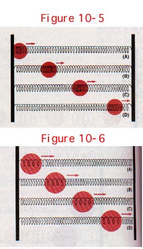
Figure 10-5. (Top) A compression pulse traveling along an elastic medium.
Figure 10-6. (Bottom) A rarefaction pulse traveling along an elastic medium.
Transverse displacements are across the path of propagation.
Longitudinal displacements are along the path of propagation.
10.5 Periodic Waves We have examined the effect of a single, nonrecurring wave disturbance on one end of a long, rigidly mounted spring. Now let us consider what happens if similar disturbances are repeated periodically. Suppose we attach the left end of a long spring to a mass suspended by a second spring as in Figure 10-7.
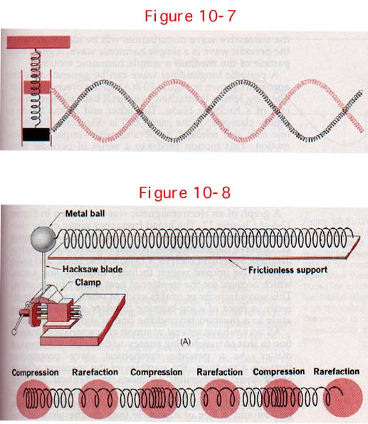
Assume that the mass can move up and down without friction between its vertical guides. If the mass is pulled down slightly and then released, it will vibrate within the guides with simple harmonic motion.
Such a motion is periodic. That is, the mass repeats its motion once every certain time interval T, called the period of vibration. Since the vibrating mass is attached to the end of the long spring, it acts as a source of periodic disturbances.
A transverse wave train is generated, which moves to the right along the spring. This wave is shown in Figure 10-7 at the instant the vibrating mass is at the upper limit of its excursion and again at the instant it is at the lower limit of its excursion;
This periodic transverse wave carries energy away from the vibrating mass. Unless energy is supplied to it, the mass loses amplitude and comes to rest. In order for a source to generate a continuous wave of uniform amplitude, energy must be supplied to the source at the same rate as the source transmits energy to the medium.
Then the successive wave disturbances will be identical. When the periodic wave is a simple harmonic wave, it gives each particle of the medium a simple harmonic motion.
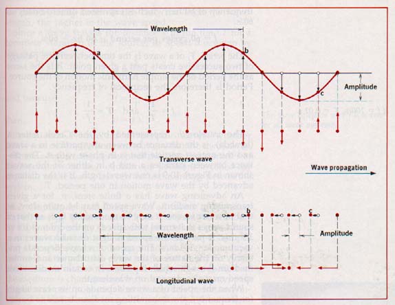
A periodic longitudinal wave can be generated by apparatus shown in Figure 10-8(A) above. The long spring is attached to a metal ball fastened to end of a hacksaw blade. The other end of the blade is rigidly clamped. If the metal ball is displaced slightly one side and released, it vibrates with simple harmonic motion.
This motion produces a series of periodic compressions and rarefactions in the spring, and periodic longitudinal wave. This is illustrated in 10-8(B). Tn order for the successive wave disturbances to be identical, energy must be provided to the source at same rate it is transmitted by the wave.
10.6 Characteristics of Waves The characteristics properties of waves discussed in the remaining sections this chapter are descriptive of all waves. An elastic medium is required for the propagation of mechanical but not for that of electromagnetic waves.
The propagation of electromagnetic waves in free space is dramatically illustrated by the transmission of information back to earth by space probes from the outer regions of our solar system.
For the transmission of electromagnetic waves, periodic oscillations of accelerating electrons in a conductor (such as an antenna) give rise to periodically reversing electric and magnetic fields that propagate in free space away from their source at the speed of light (300,000 km/s).
The frequency, f, of a periodic wave is the number of crests (or troughs) passing a given point in unit time. It is the same as the frequency of the simple harmonic motion of the source and is conventionally expressed in terms of the vibrating frequency of the source.
Thus the frequency of a motion is the number of vibrations, oscillations, or cycles per unit of time. The SI unit of frequency is the hertz (hz). One hz is equivalent to the expression "one cycle per second."
Note that "cycle" is an event, not a unit of measure. Therefore it is not a part of the dimensional structure of the hertz. The dimension of the hertz is simply s-l. For example, a wave generated at 60 cycles per second has a frequency of 60 hz, which is expressed dimensionally 60/s.
f = 60 cycles per second = 60 hz = 60/s
The period, T, of a wave is the time between the passage of two successive crests past a given point. It is the as the period of the simple harmonic motion of the source.
Period is therefore the reciprocal of frequency.
f = 1/T and T = 1/f
The wavelength, represented by the Greek letter, λ, (lambda), is the distance between any particle in a wave and the nearest particle that is in phase with it.
The distance between particles a and b in either of the waves: shown in Figure 10-9 is one wavelength. It is the distance advanced by the wave motion in one period, T.
An advancing wave has a finite speed, v, for a given transmitting medium. Wave speed may be quite slow, as that of water waves. It may be moderately fast, as that of sound waves that travel with speeds on the order of 350 m/s. It may be the speed of light or radio waves in a vacuum, 3 x 10⁸ m/s.
The speed of a wave depends primarily on the nature of the wave disturbance and on the medium through which it passes. In certain media, wave speed may also depend on wavelength.
When the speed of a wave depends on its wavelength: (or frequency), the transmitting medium is said to be dispersive. A glass prism disperses (separates) a beam of white light into a color spectrum as the light of different wavelengths emerges along diverging paths.
Glass is a dispersive medium for light waves. We can observe rainbows because water droplets in the atmosphere disperse sunlight in the same way. In fact, all electromagnetic waves propagating through matter, but not through a vacuum, show dispersion.
Water is highly dispersive for surface waves, and the wave speed can change significantly with wavelength. Ripples produced by a very gentle wind or vibrations of high frequency have very short wavelengths.
The wave speed is governed by the surface tension of the liquid, which is a measure of the tendency of the surface to resist stretching. In this case, the shorter the wavelength, the higher is the wave speed.
A strong steady wind may produce surface waves of very long wavelength. Here, the wave speed is governed by gravity, which provides a restoring force. Such waves are called gravity waves. In this case, the longer the wavelength, the higher is the wave speed.
Here is the formula for relating velocity with frequency and wavelength:
![]()
This equation is true for all periodic waves, whether transverse or longitudinal, no matter what the medium is. The maximum displacement of the vibrating particles of the medium from their equilibrium positions is called the amplitude of the wave. It is related to the energy flow in the system.
10.7 Amplitude and Energy In all forms of traveling waves, energy is transmitted from one point to another. By expending energy, a vibrating source can cause a harmonic disturbance in a medium. The energy expended per unit of time depends on the amplitude, the frequency, and the mass of the particles of the medium at the source.
Simple harmonic motion (vibrational motion) of a particle of the medium is characterized by an amount of energy, part kinetic and part potential, that the particle has at any instant. The disturbance is transferred through the medium because of the influence that a particle has on other particles adjacent to it. Thus the wave carries energy away from the source.
Assuming no losses in the system, the energy transported by the advancing wave during a given time is the same as the energy expended by the source during that time. The energy transported, or the energy expended, per unit of time is the power transmitted by the wave.
If the wave amplitude is doubled, the vibrational energy is increased fourfold. Doubling the vibrating frequency has the same effect. The rate of transfer of energy, or the power transmitted by a wave system, is proportional to the square of the wave amplitude and also to the square of the wave frequency.
Surface waves on water that emanate from a point source undergo a decrease in amplitude as they move away from their source. Each advancing wave crest is an expanding circle. The energy contained in each crest is a fixed amount, and the crest is expanding. The energy per unit length of crest must decrease.
Thus the amplitude of the wave must diminish. This effect is greater for sound waves as the advancing crests are expanding spheres.
We know from experience that the amplitude of vibrating pendulum or spring gradually decreases and the vibrations eventually stop. Frictional and effects that oppose the motion slowly remove energy form the vibrating system.
Similarly, in a wave system energy is dissipated and the wave amplitude gradually diminishes. The reduction in amplitude of a wave due to the wave energy as it travels away from the source is damping. Damping effects may be quite small over relatively short distances.
WAVE INTERACTIONS
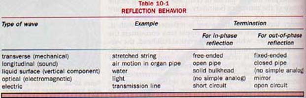
10.8 Properties of Waves In any study of wave behavior, the various properties common to all kinds of waves should be recognized. These common properties are: rectilinear propagation (straight line), reflection, refraction, diffraction, and interference.
Being familiar with the properties of waves helps to determine whether an observed phenomenon involves a wave or not. Surface waves on water are particularly useful in studying wave properties. A surface wave is easily generated, its speed is quite slow, and the transparency of the water in light allows the wave pattern to be projected on a screen.
Figure 10-13 shows how images of surface wave crests can be projected on a screen. The ripple tank has a glass bottom that allows light to be projected down through the water. The crests appear on the screen as bright regions, and troughs appear as dark regions.
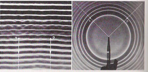
10.9 Rectilinear Propagation We can generate a train of straight waves in a ripple tank. The portions of water surface whose particles that are all in the same phase of motion are called wave fronts. The paths of the two points a and b show that the direction of the propagation of the advancing straight wave is perpendicular to the wave front.
By changing from a straight to a pointed probe, such the tip of a pencil, we can generate a train of circular waves. See Figure 10-14.
Here the advancing wave crests are expanding circles. The wave fronts are moving out in all directions from the center of disturbance. The letters a and b locate two points on an expanding crest.
Their paths show that the directions of propagation of these two segments of the advancing circular wave lie along radial lines away from center of disturbance.
This is true of all other points on circular wave crest. The radial lines are perpendicular to the segments of the wave front through which they pass.
From these experiments with the ripple tank we observe that continuous waves traveling in a uniform medium in straight lines perpendicular to the advancing wave fronts. The uniform spacing between the wave crests suggests the wave speed in the medium is constant.
Considering the speed and direction of propagation of traveling waves, we can state that the wave velocity at every point along the advancing wave front is perpendicular to the wave front.
10.10 Reflection Familiar examples of reflection are the sound echoes that return from a distant canyon wall, the reflection of light from a mirror, and the reflection of waves from the edge of a pool.
Our image as seen in a mirror appears to be reversed, right for left. The crest of a water wave is reflected from the pool side as a crest traveling in a different direction. The echo of a sound retains the character of the original sound.
About the only inference we can draw from these casual observations is that a wave is turned back, or reflected, when it encounters a barrier that is the boundary of the medium in which the wave is traveling. A close examination of the boundary conditions can reveal much more about the nature of reflection.
Suppose we generate a single straight pulse in a ripple tank that has a straight barrier placed across the tray parallel to the advancing wave front. When the pulse reaches the barrier, it is reflected back in the direction from which it came. No disturbance appears in the water behind the barrier. The paths of the incident pulse (approaching the barrier) and the reflected pulse lie perpendicular to the surface of the barrier.
The angle formed by the path of incidence and the perpendicular (normal) to the reflecting surface at the point of incidence is called the angle of incidence, i. The angle formed by the path of reflection and the normal is the angle of reflection, r. In this instance both the incident and reflected angles are 0o, and i is equal to r.
10.11 Impedance If we were to apply the same wave producing force to a light string and to a heavy rope, two entirely different displacement velocities would result. The string would experience a very large displacement velocity compared with that of the rope. We could say that the ratio of the wave-producing force to the displacement velocity is quite small for the string and quite large for the rope. In the study of waves, this ratio of the applied wave-producing force to the resulting displacement velocity is called the impedance of the medium.
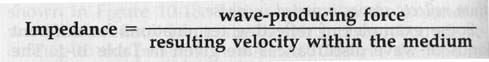
By this definition, the string is said to have a relatively low impedance and the rope a relatively high impedance. The impedance of a wave medium denotes the ease or difficulty with which a wave disturbance of given amplitude can be launched in it.
The concept of impedance is quite general and can be applied to wave media of all kinds. For a stretched string, the wave-producing force is the transverse oscillatory force applied to the end of the string. The displacement velocity is the oscillating transverse velocity imparted to the particles of the first portion of the string.
In an organ pipe, the ratio of the alternating compressional force applied to the molecules of the air to the longitudinal oscillating velocity acquired by these molecules defines the acoustic impedance of the air column.
In practical energy-transfer systems, an abrupt impedance discontinuity between two wave propagation media causes unwanted wave reflection that wastes energy. Numerous devices and techniques are used to smooth over an impedance mismatch and reduce or prevent reflections. They are called impedance transformers.
A cheerleader's megaphone is a simple approximation of an acoustic impedance transformer. It effectively matches the impedance of the air column of the throat and mouth to the free air.
The coating on an optical lens acts as an impedance transformer. It reduces reflection at the air-glass boundary and causes a greater portion of the total incident light energy to be transmitted through the lens.
There are many applications of impedance transformers in electric and electronic systems. In general, whenever a device intended to receive wave energy efficiently cannot be designed to have the same impedance as the transmitting medium, it must be coupled to the medium by means of an impedance transformer.
10.12 Refraction The properties of the medium through which a certain wave disturbance moves determine propagation speed of that disturbance. It is not surprising therefore to find that traveling waves passing from one medium into another experience a change in speed at interface (boundary) of the two media.
From the wave equation,![]() , we see that the length, lambda, λ, for a wave disturbance of a given frequency, f, is a function of its speed, v, in the medium through which it is propagating. If the speed decreases when the wave enters a second medium, the wavelength is shortened proportionally. If the speed increases, the wavelength is lengthened proportionately.
, we see that the length, lambda, λ, for a wave disturbance of a given frequency, f, is a function of its speed, v, in the medium through which it is propagating. If the speed decreases when the wave enters a second medium, the wavelength is shortened proportionally. If the speed increases, the wavelength is lengthened proportionately.
A useful aspect of water waves is the relation of the speed of surface waves to the depth of the water. Such wave disturbances travel faster in deep water than in shallow water. For a given wave frequency, the wavelength in deep water is longer than it is in shallow water. Therefore water of two different depths acts just like two different transmitting media for wave propagation.
This difference is easily observed in the ripple tank by arranging the tray so that it has two different depths of water. Then surface waves are generated that travel across the boundary of the two regions.
In Figure 10-21 the deep water representing the medium of higher propagating speed is in the lower portion of the photograph. The wave moves toward the shallow water in the upper portion. The boundary between the deep and shallow water is parallel to the advancing wave front. Thus each incident wave crest approaches the shallow region along the normal to the boundary.
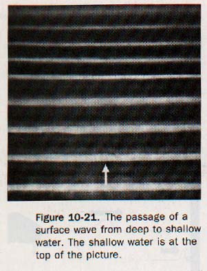
Observe that the change in wavelength is abrupt. It occurs simultaneously over the entire wave front at the boundary of the deep and shallow water. All segments of the advancing wave front change speed at the same time, and the wave continues to propagate in its original direction.
Suppose we adjust the deep and shallow regions of the tray so that the boundary is no longer parallel to the advancing straight wave but cuts diagonally across its path. This arrangement is shown in Figure 10-22.
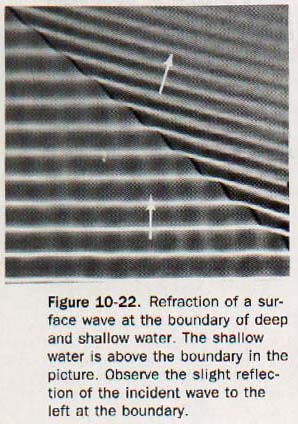
Each advancing wave crest now approaches the boundary obliquely. Adjacent segments of the wave front pass from deep to shallow water successively rather than simultaneously. At the boundary, the direction of the wave front changes; the advancing wave has undergone refraction. Refraction is the bending of the path of a wave disturbance as it passes obliquely from one medium into another of different propagation speed.
10.13 Diffraction Sounds can be heard even though they may originate around the corner of a building. However, the source of the sound disturbance cannot be seen around the corner. Rectilinear propagation appears to hold in this situation for light but not for sound. The building is an obstruction that prevents the straight-line transmission of light from the source of the sound disturbance to the observer.
Perhaps, where sound waves are concerned, the corner of the building creates a discontinuity in the transmitting medium that causes the waves to spread. Even if we find support for this idea, the question of the different behavior of light remains to be answered.
We will again use the ripple tank to observe wave behavior, this time with obstructions inserted into the transmitting medium. This may be done by placing two straight barriers across the tray on a line parallel with the straight way generator.
An aperture, or opening, is left between them approximately equal to the wavelength of the wave to be used. When a periodic straight wave is sent out, the wave pattern beyond the barrier opening appears as shown in Figure 10-24.
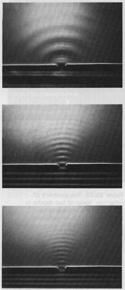
As a segment of each wave crest passes through the aperture, it clearly spreads into the region beyond the barriers. This spreading of a wave disturbance beyond the edge of a barrier is called diffraction.
Sound waves spread around the edges of doorways in the same way that water waves spread around the edges of obstructions. Audible sounds have wavelengths in air ranging from a few centimeters to several meters.
The doorway of a room or building has dimensions within this range. This suggests, but does not prove, that a discontinuity such as an aperture in the path of an advancing wave will diffract the wave if its dimensions are comparable with the wavelength of the oncoming wave.
We produced the diffraction pattern in the ripple tank with a barrier aperture approximately the same width as the wavelength of the surface wave used.
Suppose we shorten the wavelength by increasing stepwise the frequency of the wave generator. We would observe a series of patterns with waves of decreasing wavelengths.
The spreading of the wave at the edges of the aperture diminishes as the wavelength of the wave sent against them is shortened. When the wavelength is a small fraction of the width of the opening between the barriers, the wave segments passing through show little tendency to spread into the shadow regions beyond the barriers.
These observations suggest that if the wavelength is much smaller than the width of the aperture, no diffraction occurs. The part of the straight wave that passes through the opening will continue in straight-line propagation. How are these observations related to the fact that light is not diffracted at the edges of a doorway as is sound?
The speed of light in air is high, being on the order of 3 x 10⁸ m/s. We have not yet dealt with light frequencies, but if they were extremely high, light wavelengths (v/f) would be very short. Then it would not be surprising to find that light is diffracted only by apertures having very small dimensions .
Indeed, the wavelength of visible light ranges from approximately 7.5 x 10⁻⁷ m down to about 4 x 10⁻⁷ m. This range of wavelengths suggests that the diffraction of light occurs in the realm of extremely small dimensions. Diffraction phenomena associated with light waves will be presented in Chapter 15.
10.14 The Superposition Principe We have described the passage of a single pulse and a continuous wave through a medium. It is possible for two or more wave disturbances to move through a medium at the same time.
Sound waves from all the musical instruments of an orchestra move simultaneously through the air to our ears. Electromagnetic waves from many different radio and television stations travel simultaneously through regions of space to our receiving antennas, Yet, we still can listen to the sound of a particular musical instrument or select a particular radio or television station.
These facts suggest that each wave system proceeds independently along its pathway as if the other wave systems were not present. Let us consider the effects of two periodic transverse waves traveling along a taut string in the same direction.
The displacements they produce at a particular instant are shown in Figure 10-25.
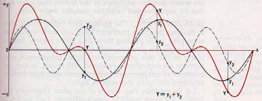
These two waves have different amplitudes and frequencies. The displacements y1 produced by one wave are represented by the black solid curve. The displacements y2 produced by the other wave are represented by the black dashed curve.
The resultant displacements Y all along the string at this instant are represented by the colored curve. These resultant displacements are determined by algebraically adding the displacements yl and y2 for every point along the string. In effect, the displacement of any particle of the medium by one wave at any instant is superimposed on the displacement of that particle by the other wave at that instant.
The action of each wave on a particle is independent of the action of the other, and the particle displacement is the resultant of both wave actions. This phenomenon is known as superposition.
The superposition principle: When two or more waves travel simultaneously through the same medium, (I) each wave proceeds independently as though no other waves were present and (2) the resultant displacement of any particle is the vector sum of the displacements that the individual waves acting alone would give it.
Providing the displacements are small, this principle holds for light and all other electromagnetic waves as well. as for sound waves and waves on a string or on a liquid surface.
The component waves yl and y2 in Figure 10-25 are simple sine waves. Observe that the frequency, .f2 wave y2 is twice the frequency of wave y1. That is,
f2 = 2f1
Either periodic wave alone would cause each particle of the string to undergo simple harmonic motion about its equilibrium point as the wave traveled along the string.
The resultant wave is also periodic. However, it has a complex, or complicated, wave form. The superposition principle makes it possible to analyze a complex wave.
10.l5 Interference The general term interference is used to describe the effects produced by two or more waves that superpose while passing through a given region. Special consideration is given to waves of the same frequency, particularly in the case of sound and light.
Interference phenomena are exclusively associated with waves. In fact, the existence of interference in experiments with light first established the wave character of light.
Let us consider two waves of the same frequency traversing the same medium simultaneously. Each particle of the medium is affected by both waves.
Suppose the displacement of a particular particle caused by one wave at any instant is in the same direction as that caused by the other wave. Then the total displacement of that particle at that instant is the sum of the separate displacements (superposition principle). The resultant displacement is greater than either wave would have caused separately. This effect is called constructive interference.
On the other hand, if the displacement effects of the two waves on the particle are in opposite directions, they tend to cancel one another. The resultant displacement of that particle at that instant is the difference of the two separate displacements and is in the direction of the larger (superposition principle).
The resultant displacement is less than one of the waves would have caused separately. This effect is called destructive interference.
If two such opposite displacement effects are equal in magnitude, the resultant displacement is zero. The destructive interference is complete. The particle is not displaced at all but is in its equilibrium position at that instant.
Notice that we have been considering the effect of two waves on the position of just one particle of the medium at one particular instant. We shall continue to fix our attention on one instant in time as we consider the displacements of many different particles of the medium in which the two waves are propagating. We find that the interference effects on different particles are different. There will appear constructive interference at some locations and destructive interference at others.
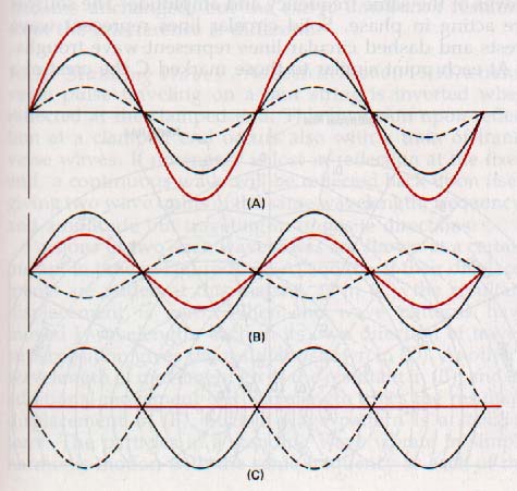
In Figure 10-26(A) two periodic waves with the same frequency and in phase are traveling in the same direction. They interfere constructively. The resultant periodic wave, shown in color, has the same frequency as the component waves but has an amplitude equal to the sum of the component amplitudes.
In Figure 10-26(B) the two periodic waves have the same frequency but are opposite in phase, that is, 180o out of phase. The displacements of the two waves are opposite in sign, and they interfere destructively.
In Figure 10-26(C) the amplitudes of the two waves are equal and the destructive interference is complete.
The arrangement of interference effects (called an interference pattern) depends on the relative characteristics of the interfering waves.
Figure 10-27 is a photograph of an interference pattern produced in a ripple tank by two identical circular waves emanating from two points. The two waves are in phase at their sources. That is, the two probes that generate the waves by their vibrations are interference pattern of water moving up and down together.

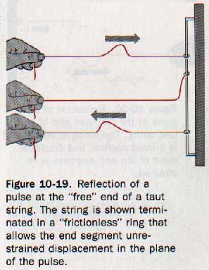
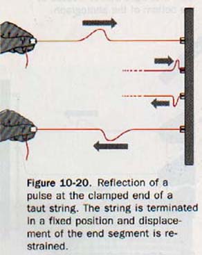
10.16 Standing Waves As seen in Section 10.10, a transverse pulse traveling on a taut string is inverted when reflected at the clamped end. This inversion upon reflection at a clamped end occurs also with a train of transverse waves.
If no energy is lost in reflection at the fixed end, a continuous wave will be reflected back upon itself giving two wave trains of the same wavelength, frequency, and amplitude but traveling in opposite directions.
Portions of two such wave trains are shown at a certain instant in time in Figure 10-29(A) and (B). If their displacements are added at this instant, as in (C), the resultant displacement is zero. When the wave patterns have moved a wavelength, each in its own direction of travel, superposition gives the resultant shown in (D).
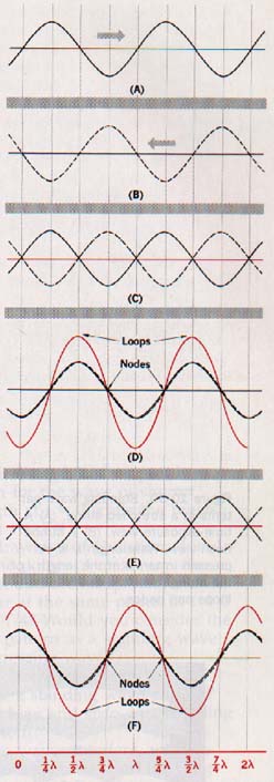
Another a wavelength of movement gives the resultant in (E), and an additional movement of a wavelength gives the resultant displacement in (F). Such a wave pattern is a standing wave. The particles in a standing wave vibrate in simple harmonic motion with the same frequency as each of the component waves.
A standing wave is produced by the interference of two periodic waves of the same amplitude and wavelength traveling in opposite directions. No standing wave can be produced of the two waves have different wavelengths.
The points of no vibration are called nodes, the parts of maximum displacement are called loops or antinodes.
1. Figure 10-30(A) illustrates a time-exposure view showing the envelopes of the standing waves. Part (B) is a strobe-flash view showing positions of the strings at different instants of time. In a standing wave, particles of the string at the nodes are continuously at rest.
Energy is not transported along the string, but remains "standing" in the string. The energy of each particle remains constant as that particle executes its simple harmonic motion. When the string is straight, or undistorted, particles have their maximum velocities and the energy is all kinetic. The energy is all potential when the string has its maximum displacement and all particles are momentarily at rest.
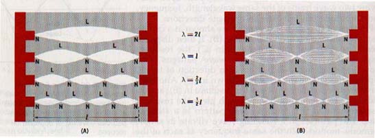
Standing waves are established in water, in air, or in other elastic bodies, just as they are in taut strings. Standing waves can also be produced with electromagnetic waves. A standing wave pattern can occur in a circular ripple tank in which a periodic circular wave is generated at the center of the tank.
Nodal rings appear where the surface of the water is at rest. The surface oscillates up and down between the nodal rings. Many vibrating objects vibrate normally in a way that establishes standing waves in the object. The strings or the air columns of musical instruments establish various modes of standing waves.
SUMMARY
Energy can be transferred by the movement of materials or objects, by the motion of particles, by the flow of gases or liquids, and by waves. Energy is transferred by waves without the transport of matter. Waves that require a material medium for their transmission are called mechanical waves.
Electromagnetic waves can travel through matter but a material medium is not required for their transmission.
A pulse is a single wave disturbance. A continuous wave results from a wave disturbance that recurs periodically.
Mechanical waves in which the particles of the transmitting medium are displaced perpendicular to the direction in which the wave travels are called transverse waves.
Those in which the particles of the medium are displaced parallel with the wave direction are longitudinal waves.
Waves have common characteristics such as phase, frequency, period, wavelength, speed, and amplitude. A wave's velocity is the product of its frequency and its wavelength in the medium. Transmission media in which the speed of a wave is dependent on its frequency are said to be dispersive.
Some of the common properties of waves are rectilinear propagation, reflection, refraction, diffraction, and interference.
Superposition occurs when two or more wave disturbances move through a medium at the same time.
Standing waves are produced by the interference of two periodic waves of the same amplitude and wavelength and traveling in opposite directions.
VOCABULARY
amplitude, angle of incidence, angle of reflection, damping, diffraction, dispersive medium, elastic medium, frequency, impedance, interference, longitudinal wave, mechanical wave, period, periodic motion, phase, rectilinear propagation, reflection refraction, simple harmonic motion, standing wave, superposition, transverse wave, wave, wave crest, wave front, wavelength, wave trough.
Ah Yaz Indeed!
 Assignment Sheet for this Research Text Only.
 Go to Textbook Assignments for Portfolio:
.................................First Semester
.................................Second Semester